
Self-Clinching Nut Dimensions — Inch Series Ladder (#4-40 to 1/4-20)
Head, sheet and installation data for self-clinching nuts across the six-size inch ladder #4-40, #6-32, #8-32, #10-24, #10-32 and 1/4-20 — head diameter, unthreaded length, minimum sheet thickness, edge distance, installation hole size and tightening torque — transcribed row-for-row from the collected chart.
Last updated: 2026-11
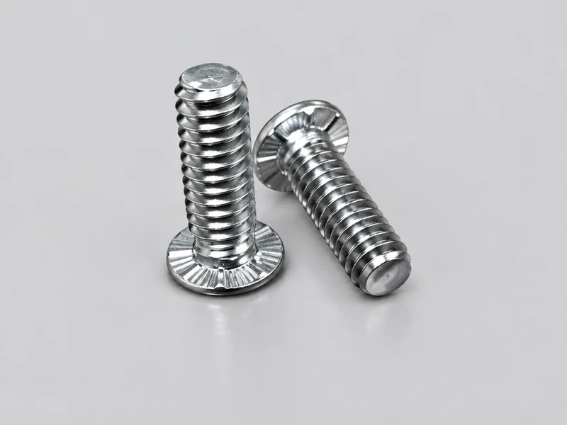
Specifications
A self-clinching nut turns a thin sheet into a threaded boss: the nut is pressed into a punched or drilled hole, its knurled or serrated shoulder displaces sheet material into a retaining groove, and the sheet — as thin as 0.040 in on the small sizes in this chart — carries a reusable machine thread it could never hold tapped. The collected chart tabulates the six-size inch ladder a design needs to lay the hole out: #4-40, #6-32, #8-32, #10-24, #10-32 and 1/4-20, each with head diameter max/min, unthreaded length max/min, minimum sheet thickness, minimum edge distance from hole centre to panel edge, the installation hole size (a +.003/-.000 tolerance band — the clinch depends on hole size within a few thousandths) and the maximum recommended tightening torque in service. Reading the ladder: head diameters run from 0.204/0.172 in on #4 up to 0.344/0.312 on 1/4; the #4 needs only a 7/32 in hole and 0.040 in sheet; 1/4-20 steps up to a 5/16 in hole, 0.062 in sheet and 58 in-lb of torque. Two reading notes carried from the source: the size column prints "10" twice — TPI 24 and 32 distinguish the 10-24 and 10-32 variants (flagged) — and the 1/4 row's unthreaded-length cell prints "135" where the rest of the column runs decimals, almost certainly a lost decimal point (.135), reproduced verbatim and flagged rather than silently repaired. Push-out and torque-out performance, plating and the metric ladder are not tabulated here — per RFQ.
| Family | Self-clinching nuts, inch series; 6-size ladder #4-40 through 1/4-20 (TPI 40/32/32/24/32/20) |
|---|---|
| Per-row data (in) | Head diameter max/min, unthreaded length max/min, min sheet thickness, min edge distance to hole centre, hole size +.003/-.000, max tightening torque (in-lb) |
| Installation hole | Chart-printed sizes: 7/32 (#4) up to 5/16 (1/4-20), tolerance +.003/-.000 — hole accuracy is the clinch, so the printed band governs the panel layout |
| Sheet thickness | Minimum 0.040 in on #4–#10, 0.062 in on 1/4-20 — thinner sheet needs the thin-sheet variant series, per RFQ |
| Torque ceiling (in service) | 5 in-lb (#4) scaling to 58 in-lb (1/4-20) as printed — assembly torque above this risks spin-out of the clinch |
| Not tabulated | Push-out/torque-out performance, plating, metric ladder, stainless/steel variants — per RFQ |
| Nominal Size | Threads Per In. | Head Dia. (A) Max | Head Dia. (A) Min | Unthreaded Length (B) Max | Unthreaded Length (B) Min | Min. Sheet Thickness | Min. Edge Distance to Hole Centre | Hole in Sheet +.003/-.000 | Max. Tightening Torque (in.-lb) |
|---|---|---|---|---|---|---|---|---|---|
| 4 | 40 | .204 | .172 | .085 | .075 | .040 | 7/32 | .111 | 5 |
| 6 | 32 | .235 | .203 | .090 | .080 | .040 | 1/4 | .137 | 9 |
| 8 | 32 | .266 | .234 | .090 | .080 | .040 | 9/32 | .163 | 17 |
| 10 | 24 | .282 | .250 | .090 | .080 | .040 | 9/32 | .189 | 24 |
| 10 | 32 | .282 | .250 | .090 | .080 | .040 | 9/32 | .189 | 27 |
| 1/4 | 20 | .344 | .312 | 135 | .125 | .062 | 5/16 | .249 | 58 |
- Row 5 (10): The size column prints "10" twice (TPI 24 and 32 distinguish the two #10 variants, i.e. 10-24 and 10-32); designation suffixes are the standard reading of the ladder.
- Row 3 (8): The #4 (row 0) B-max column prints "135" for the 1/4 size where the rest of the column runs decimals (.085–.090) — the source cell almost certainly lost its decimal point (.135); reproduced verbatim, flagged.
Materials
- Steel and stainless body variants exist across the family; the chart is geometry data — state panel material and hardness at RFQ (clinching needs the panel softer than the insert)
Ordering & documentation
Documents
Shipments of Self-Clinching Nut Dimensions — Inch Series Ladder (#4-40 to 1/4-20) are backed by Mill Test Certificate (MTC), Dimensional Report, Salt Spray Test Report on request, with full batch traceability from raw material to finished product. Quality management for Self-Clinching Nut Dimensions — Inch Series Ladder (#4-40 to 1/4-20) orders follows the owner-confirmed compliance list: ISO 9001:2015, RoHS, REACH. Exact document sets are confirmed on the order.
Quotation
- The product family (Self-Clinching Nut Dimensions — Inch Series Ladder (#4-40 to 1/4-20)), product standard/designation and drawing or part number.
- The dimensions that apply to this part — such as size, pitch, length, thickness, fit, grip or groove geometry.
- Material/grade, heat-treatment condition and surface finish, together with the service environment.
- Quantity per size, delivery destination and required test or traceability documents.
Sample & supply
Minimum order quantities and lead times for self-clinching nut dimensions — inch series ladder (#4-40 to 1/4-20) are confirmed at quotation — send series, thread size and parent sheet thickness on the RFQ and the quote will carry a firm schedule; sample availability is confirmed with the quotation.
Storage & shipping
Self-Clinching Nut Dimensions — Inch Series Ladder (#4-40 to 1/4-20) are packed for export and shipped factory-direct to buyers in Europe, Asia, the Americas and the Middle East. Store self-clinching nut dimensions — inch series ladder (#4-40 to 1/4-20) dry and protected until installation, and keep coated parts in their packaging until use; specific packing and preservation requirements can be stated on the order and confirmed at quotation.
Frequently asked questions
Why is the installation hole tolerance so tight on a self-clinching nut, and what happens at the panel-design level if it is missed?
The clinch is a cold-flow operation: pressing the nut displaces the panel material around the hole into the nut's retaining groove, and the amount of displacement — the whole strength of the joint — is set by the gap between hole and nut. The chart's +.003/-.000 band exists because a hole even a few thousandths large leaves the groove under-filled and the nut can push out or spin under torque; a hole too small over-presses, flares the head or cracks hard panels. So the hole is a machined feature, not a clearance cutout: the panel drawing should carry the printed size with its tolerance (7/32 on #4 up to 5/16 on 1/4-20), ideally punched and sized or drilled, with the edge-distance minimum respected so the displaced material has somewhere to go without bulging the panel edge. The other chart figure that matters at design time is the torque ceiling — 5 in-lb at #4 scaling to 58 in-lb at 1/4-20 — which is the in-service limit for the assembly screw, not the installation press force. What the chart cannot decide: whether the panel alloy clinches cleanly (hardened or high-strength panels need a different insert family), the push-out/torque-out numbers for a load-case calculation, or plating stack-ups that change hole size — those come back as RFQ answers with the panel spec.
Commercial terms for clinch nuts?
Commercial terms are confirmed at quotation.
Request a Quote
Get factory-direct pricing from the manufacturer.
What to include in your Self-Clinching Nut Dimensions — Inch Series Ladder (#4-40 to 1/4-20) inquiry
- ✓ Identify the clinch-nut, stud or standoff series and the internal thread size.
- ✓ Specify parent-sheet material, hardness and actual thickness, not gauge alone.
- ✓ Provide prepared-hole diameter, edge distance and hole-to-hole spacing from the panel drawing.
- ✓ State locking/non-locking requirement, installation press/tooling and any push-out or torque-out acceptance data.
- ✓ Factory-direct pricing for your Self-Clinching Nut Dimensions — Inch Series Ladder (#4-40 to 1/4-20)
- ✓ Standard and custom specifications
- ✓ Factory-direct export to buyers in Europe, Asia, the Americas and the Middle East
- ✓ Full fastener family support