
Retaining Rings
Metric DIN 471 external and DIN 472 internal retaining rings (circlips) are thin, circular, metal stampings used to prevent movement between mating components, reducing vibration and maintaining proper position while permitting easy disassembly.
Last updated: 2026-11
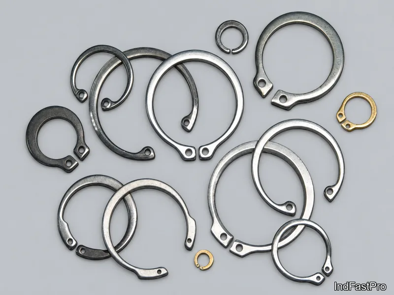
Specifications
Industry-standard reference ranges — availability confirmed per quotation; not a stocked-range claim.
| Types | DIN 472 internal retaining rings (aka circlips) | DIN 471 external retaining rings (aka circlips) |
|---|
Reference notes (collected source statements, not supply-scope values):
- standard:: DIN standards continue to be used for parts which do not have ISO equivalents or for which there is no need for standardization (DIN 472, DIN 471)
Materials
- A2 stainless steel
Selection guidance
External versus internal retaining rings, the groove data a drawing must carry, and what to confirm before ordering.
External (DIN 471) or internal (DIN 472)
Both standards cover thin, circular metal stampings that prevent movement between mating components; the difference is where the groove sits. DIN 471 external rings are assembled axially onto a shaft and seat into a groove machined on the outside of the shaft. DIN 472 internal rings are assembled axially into machined grooves in housings and bores, and the tapered section design allows uniform circular deformation and even contact with the groove surface. Both permit easy disassembly by removing the ring.
The collected specification sheets attribute A2 stainless steel to the rings and note that neither DIN 471 nor DIN 472 has an ISO equivalent, so the DIN designations remain the ordering vocabulary. Quote the standard that matches where your groove is machined — shaft groove takes DIN 471, bore groove takes DIN 472.
Groove data and load columns
Every dimension row in the collected sheets pairs the ring geometry (thickness s, clip diameter d3, edge distance d5) with the groove data the drawing must machine: groove diameter d2 and groove width m. The sheets print an H13 tolerance band for the groove diameter column on the 471 sheet, with per-size band markers (h10)/(h11)/(h12)/(h13) on the smaller sizes, and (H11)/(H12)/(H13) markers on the 472 sheet. Sampled verbatim: at nominal shaft diameter 16 mm the 471 sheet lists groove d2 = 15.2 mm and width m = 1.1 mm; at 80 mm, d2 = 76.5 mm and m = 2.65 mm; the 472 sheet lists groove d2 = 9.4 mm at nominal bore 9 mm and d2 = 104 mm at nominal bore 100 mm.
The sheets also tabulate supplementary load columns per size (FN, FR, FRg and the nabl column). In the collected extraction the supplementary column order is layout-ambiguous, so those figures are quoted as whole rows on request rather than rendered as labeled values — ask for the row for your size and it is confirmed from the sheet before quotation. The sheets also list the nominal size of retaining-ring pliers per DIN 5254 per size band.
How a retaining ring assembly fails: the groove goes first
The ring itself is rarely the weak link: grooves generally yield before rings shear, so the thrust load capacity of the assembly is governed by the groove, not the stamping. Thrust load capacity is directly proportional to groove depth — a groove machined shallower than the specified d2 dimension silently de-rates the whole assembly, and rings used where specific limits are exceeded show a marked decrease in thrust capacity unless groove depth, ring width, or groove-material strength is increased.
Shearing does occur in specific setups: when the ring and a retained part are both loaded past their compressive yield strengths, or when the load passes through square-cornered retained parts and grooves in line-to-line contact. That is why the published guidance carries different safety factors by condition — a factor of two where square-cornered parts meet the groove or side clearance is small, a factor of four where chamfers and radii fall within recommended values and clearance is adequate. Chamfer guidance from manufacturers is exactly that: guidelines, not verified properties of your assembly.
Groove position has its own limit: a groove machined too close to the end of a shaft or bore may shear the edge out entirely. The general rule of thumb is to keep three times the groove depth of material between the groove and the end of the housing or shaft — less than that and the retaining lip becomes the failure surface.
Rotation and speed: where ring types stop being interchangeable
Stamped tapered-section rings (the DIN 471/472 type on this page) and spiral-wound rings are not interchangeable selection choices. Spiral retaining rings offer continuous adjustment along shaft length and eliminate groove machining requirements — but the use of spiral wound rings to retain a rotating part must be limited to applications with light thrust loads and rotation in only one direction, for both static and dynamic loading. A rotating shaft under real thrust is stamped-ring territory.
Speed is a separate limit from thrust. Proper functioning depends on the ring remaining seated on the groove bottom, and centrifugal loading can overcome the initial cling built into an external ring and cause it to lose its grip — the allowable steady-state speed has to be calculated for the ring-and-groove geometry, not assumed. Parts that spin in their grooves under sudden acceleration leave evidence: a ring which has spun in its groove will exhibit bright spots or a wear line along the surface which contacts the groove wall. That mark is an inspection finding, not a cosmetic one.
Groove quality decides how much of the rated capacity survives: retaining-ring groove walls should be perpendicular to the shaft or bore axis, with square corners on the top edge and radii at the bottom within the manufacturer tolerance. Where the allowable ring deflection is exceeded, experimental data indicates rings tend to pop out of their grooves beyond 18 degrees — another reason chamfered retained parts and correctly radiused grooves are load-bearing details, not finish details.
What this page cannot verify
The page lists published groove dimensions and the selection boundary between ring types; it cannot verify the thrust capacity of your assembly. Published or calculated static thrust loads are only valid for a groove whose depth, chamfers, radii, edge margin and material yield strength match the conditions the calculation assumes — eccentric loading (a retained-part face not parallel to the ring because of machining error, or a part cocking under external force) and impact-induced vibration are frequently encountered and frequently unanticipated. Confirm your groove design and load case against the ring manufacturer’s engineering data and your engineer of record; a quoted ring size is not a verified axial-load rating for the joint.
How do you check a DIN 471 or DIN 472 size row against your drawing?
Start with the range boundary, because it decides whether a circlip exists for your part at all. The DIN 471 dimension table runs from nominal shaft diameter 3 mm upward (the collected sheet also lists assembly pliers per DIN 5254 per size band), while the DIN 472 table starts at nominal bore 8 mm — the first row of the 472 sheet is d1 = 8 with ring thickness s = 0.8 mm, groove d2 = 8.4 mm and groove width 0.9 mm. A bore below 8 mm has no DIN 472 ring to select; on very small shafts the DIN 6799 E-ring family takes over, dimensioned at nominal shaft diameters 0.8, 1.2 and 1.5 mm with ring height h and groove dimension n published as nominal/max/min triplets (at d = 0.8: h 0.2 nominal, 0.18 to 0.22).
Then check the tolerance direction. On the DIN 983 grid the groove diameter d2 carries a downward-only deviation — at nominal 16 mm the groove is 15.2 mm with a 0/-0.11 band, and the band widens rather than flipping sign as sizes grow (0/-0.13 at d1 = 20, 0/-0.21 at d1 = 23). The groove is machined so it is never larger than nominal: an oversize groove is not a size you can correct by picking a different ring, it is a scrapped part. Compare your measured groove diameter against the nominal-and-minus band, not against nominal alone.
Finally, read the load column for what it actually rates. The FN column is the load-bearing capacity of the groove — at a yield point of the grooved material of 200 MPa — not the strength of the ring stamping. A ring installed in a soft housing inherits the housing’s low groove capacity regardless of the ring’s own FR figure, so the material of the grooved part enters the selection as early as the ring size does.
Does a larger ring always handle more? Load rises while speed falls.
Not in both axes at once. Across the DIN 983 rows the groove-load column FN rises monotonically with shaft size — 3.26 kN at d1 = 16, 5.06 kN at 20, 7.05 kN at 25 — so a larger ring does carry more axial load. But the nabl speed-limit column falls over the same span: 45400 min⁻¹ at d1 = 16, 30400 at 20, 24200 at 25. The trade is structural: a bigger ring seats a deeper groove and holds more thrust, but presents more mass and radius at the joint, and lifts off the groove bottom at lower rotational speed.
The practical consequence: when the shaft spins, size up for thrust and check the speed column in the same pass. A selection that satisfies the load row can still fail the speed row as the diameter grows, and there is no ring variant on this page that escapes the trade — only a smaller assembly or a different retaining method moves both limits together.
Which stainless designation covers a retaining ring?
The same scheme as threaded stainless fasteners. The DIN 471 sheet documents stainless ring material under the A2-70-style designation: stainless steels divide into austenitic, ferritic and martensitic groups, with austenitic by far the most common (>90% of commercial fasteners), and the group plus strength class written as a four-digit sequence of letters and numbers (e.g. A2-70), governed by DIN EN ISO 3506. When a drawing calls out A2-70 on a retaining ring, it is invoking that same screw-and-nut standard, so the strength-class expectations transfer.
The wider ring family follows the same groups: the collected DIN 984 internal-ring listing offers steel and stainless in A1, A2 and A4 alongside carbon steel and mild steel — so the austenitic A2/A4 choice familiar from threaded work is available across circlip types, not only on the 471/472 sheets. As with any material callout, confirm the certificate class at ordering rather than assuming the group from the ring form.
Ordering & documentation
Documents
Shipments of Retaining Rings are backed by Mill Test Certificate (MTC), Dimensional Report, Salt Spray Test Report on request, with full batch traceability from raw material to finished product. Quality management for this retaining rings line follows the owner-confirmed compliance list: ISO 9001:2015, RoHS, REACH. Exact document sets are confirmed on the order.
Quotation
- External shaft ring (for example DIN 471) or internal bore ring (for example DIN 472), plus ring type.
- Nominal shaft or housing-bore diameter and the groove diameter, width and tolerances.
- Ring material, heat treatment and finish for the service environment.
- Axial load, rotational speed, assembly access/pliers and quantity per size.
Sample & supply
Minimum order quantities and lead times for retaining rings are confirmed at quotation — send ring type, shaft or housing diameter and groove dimensions on the RFQ and the quote will carry a firm schedule; sample availability is confirmed with the quotation.
Storage & shipping
Retaining Rings are packed for export and shipped factory-direct to buyers in Europe, Asia, the Americas and the Middle East. Store these retaining rings dry and protected until installation, and keep coated parts in their packaging until use; specific packing and preservation requirements can be stated on the order and confirmed at quotation.
Ring standards & types
Each retaining-ring standard defines its own shaft/bore and groove geometry. Distinguish external shaft rings from internal bore rings and verify groove diameter, width and tolerances.
- DIN 471 External Retaining Rings (for Shafts)
- DIN 472 Internal Retaining Rings (for Bores)
- DIN 6799 Retaining Rings for Shafts (E-Clips)
- External Retaining Rings (Imperial, Series 2100-5100)
- Internal Retaining Rings (Imperial, Series 2000-5000)
- Crescent Retaining Rings for Shafts (Series 2103–5103)
- E-Rings for Shafts, Heavy Duty (Series 2144–5144)
- Heavy Duty External Retaining Rings (Series 2160–5160)
- External Inverted Retaining Rings
- External Shaft Rings, Poodle Style
- DIN 705 Adjusting Rings
- DIN 984 Internal Retaining Rings with Lugs
- DIN 983 External Retaining Rings with Lugs
Engineering references
Dimension charts and technical reference tables for retaining rings — engineering aids for selection and verification, not a statement of the orderable range. Supply availability is confirmed per quotation.
- External Self-Locking Retaining Rings — Thrust Load (Inch Series) — engineering reference
- Internal Self-Locking Retaining Rings — Thrust Load (Inch Series) — engineering reference
- Retaining Ring Thrust Load Capacity (Ring vs Groove) — engineering reference
Frequently asked questions
DIN 471 or DIN 472 — which do I quote?
It follows the groove: DIN 471 external rings seat into a groove machined on the outside of a shaft; DIN 472 internal rings seat into a groove machined inside a housing or bore. Both assemble axially and remove with retaining-ring pliers, and the collected specification sheets attribute A2 stainless steel to both and note neither has an ISO equivalent.
What groove data does a retaining-ring drawing need?
Groove diameter and groove width, machined to the tolerance band the standard prints for your size — the collected sheets carry an H13 band for the 471 groove column with per-size markers on smaller sizes, and (H11)/(H12)/(H13) markers on the 472 sheet. For example, a 16 mm shaft takes a 15.2 mm groove at 1.1 mm width per the collected sheet; a 100 mm bore takes a 104 mm groove at 3.2 mm width. Sampled rows per standard are on the DIN 471 and DIN 472 specification pages.
What is the MOQ and lead time for retaining rings?
Commercial terms for this family are confirmed at quotation together with sizes and material — state the standard (DIN 471 or DIN 472), the shaft or bore nominal diameter, groove diameter and width, material, and quantity per size on the RFQ.
Request a Quote
Get factory-direct pricing from the manufacturer.
What to include in your Retaining Rings inquiry
- ✓ Identify external shaft rings (for example DIN 471) or internal bore rings (for example DIN 472), plus ring type.
- ✓ Give nominal shaft or housing-bore diameter and the groove diameter, width and tolerances.
- ✓ State ring material, heat treatment and finish for the service environment.
- ✓ Describe axial load, rotational speed, assembly access/pliers and quantity per size.
- ✓ Factory-direct pricing for your Retaining Rings
- ✓ Standard and custom specifications
- ✓ Factory-direct export to buyers in Europe, Asia, the Americas and the Middle East
- ✓ Full fastener family support