
DIN 271 Tangential Keys for Constant Loads (d 60 – 630)
DIN 271 tangential keys and keyways for constant loads — the same paired tangent-key construction as DIN 268 for non-reversing drives, tabulated from shaft 60 to 630 mm with key widths b from 19.3 to 157.1 and keyway depths per shaft size.
Last updated: 2026-11
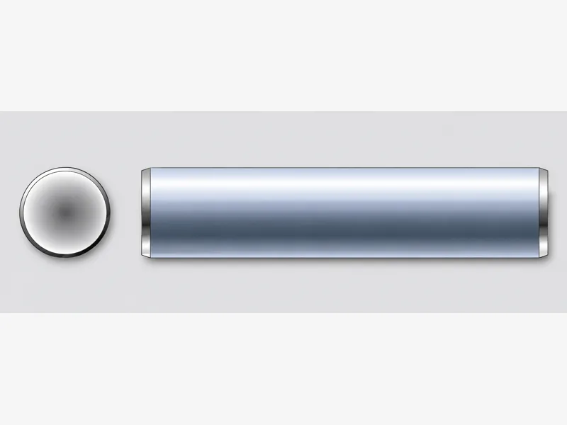
Specifications
DIN 271 is the constant-load member of the DIN tangential-key pair: the same two round-ended keys laid tangentially near the shaft surface, working in compression at the largest lever arm the shaft offers, but specified for drives whose torque does not reverse — continuous conveyors, rolling lines, main drives running one direction. Running in one direction lets the pair sit closer to the neutral axis, and the tabulated ladder reflects that: it starts at shaft 60 mm (DIN 268, the shock-load variant, starts at 100), and at the same shaft size the key is lighter — at d 100 the DIN 271 row is b 28.6 / keyway 9.3 against DIN 268's b 30 / keyway 10.3. The collected grid runs 43 rows from d 60 to d 630, carrying per size the key width b (19.3 at d 60 up to 157.1 at d 630), the c value and the keyway depth d (7.3 at d 60 up to 42.4 at d 630, again a consistent 0.3–0.5 over c). Source-reading notes before quoting: the source page misprints DIN 268's title above this table (the data matches the constant-load ladder printed on both collected pages — see the table flag), and the source prints no material, finish or length line. Key length is a per-order dimension; everything outside the tabulated shaft range is per RFQ.
| Standard / scope | DIN 271 tangential keys and tangential keyways for constant loads ("gleichbleibende Beanspruchung") — the source page prints DIN 268's title line above this table (title defect carried as a flag); the data matches the constant-load ladder, publication date 09/1974, no withdrawal mark printed |
|---|---|
| Shaft range (d) | 60 to 630 mm, 43 tabulated rows: 60/63/65/70/71/75/80/85/90/95/100/110/120/125/130/140/150/160/170/180/190/200, then the standard heavy series through 630 |
| Key width (b) | 19.3 mm at d 60 rising to 157.1 mm at d 630 — lighter sections than DIN 268 at the same shaft size (b 28.6 vs 30 at d 100; b 51 vs 60 at d 200), the constant-load allowance |
| Keyway depth (d keyway) | 7.3 at d 60 to 42.4 at d 630, consistently 0.3–0.4 above the c value on every row — keyways are cut to the d column of the selected row |
| Not tabulated | No material, finish, key length or tolerance line is printed on the source page; key length is a per-order dimension — per RFQ |
| Key Width (b) | c (key) | d (keyway) | Shaft Diameter (d) |
|---|---|---|---|
| 19.3 | 7 | 7.3 | 60 |
| 19.8 | 7 | 7.3 | 63 |
| 20.2 | 7 | 7.3 | 65 |
| 21 | 7 | 7.3 | 70 |
| 22.5 | 8 | 8.3 | 71 |
| 23.2 | 8 | 8.3 | 75 |
| 24 | 8 | 8.3 | 80 |
| 24.8 | 8 | 8.3 | 85 |
| 25.6 | 8 | 8.3 | 90 |
| 27.8 | 9 | 9.3 | 95 |
| 28.6 | 9 | 9.3 | 100 |
| 30.1 | 9 | 9.3 | 110 |
| 33.2 | 10 | 10.3 | 120 |
| 33.9 | 10 | 10.3 | 125 |
| 34.6 | 10 | 10.3 | 130 |
| 37.7 | 11 | 11.4 | 140 |
| 39.1 | 11 | 11.4 | 150 |
| 42.1 | 12 | 12.4 | 160 |
| 43.5 | 12 | 12.4 | 170 |
| 44.9 | 12 | 12.4 | 180 |
| 49.6 | 14 | 14.4 | 190 |
| 51 | 14 | 14.4 | 200 |
| 57.1 | 16 | 16.4 | 220 |
| 59.9 | 16 | 16.4 | 240 |
| 64.6 | 18 | 18.4 | 250 |
| 66 | 18 | 18.4 | 260 |
| 72.1 | 20 | 20.4 | 280 |
| 74.8 | 20 | 20.4 | 300 |
| 81 | 22 | 22.4 | 320 |
| 83.6 | 22 | 22.4 | 340 |
| 93.2 | 26 | 26.4 | 360 |
| 95.9 | 26 | 26.4 | 380 |
| 98.6 | 26 | 26.4 | 400 |
| 108.2 | 30 | 30.4 | 420 |
| 110.9 | 30 | 30.4 | 440 |
| 112.3 | 30 | 30.4 | 450 |
| 113.6 | 30 | 30.4 | 460 |
| 123.1 | 34 | 34.4 | 480 |
| 125.9 | 34 | 34.4 | 500 |
| 136.7 | 38 | 38.4 | 530 |
| 140.8 | 38 | 38.4 | 560 |
| 153.1 | 42 | 42.4 | 600 |
| 157.1 | 42 | 42.4 | 630 |
- Row 1 (19.3): The source page for DIN 271 misprints the DIN 268 title line ("alternating shock loads") above this table; the data itself matches the constant-load ladder (b 19.3–157.1, shaft 60–630) printed as the second table on both collected pages. The title defect is recorded as a source note, not corrected into the caption.
Materials
- The source page prints no makings line, so this page makes no material claim beyond the dimension grid. Tangential keys are supplied in steel; grade and certificate are RFQ decisions for the drive engineer, not assumptions from a dimension table. State the shaft diameter, key width b, the constant-load designation explicitly (DIN 271, not DIN 268 — the ladders differ at the same shaft size), the mating keyway depths, material and certificate requirement, and quantity per size — commercial terms are confirmed at quotation.
Ordering & documentation
Documents
Shipments of DIN 271 Tangential Keys for Constant Loads (d 60 – 630) are backed by Mill Test Certificate (MTC), Dimensional Report, Salt Spray Test Report on request, with full batch traceability from raw material to finished product. Quality management for DIN 271 Tangential Keys for Constant Loads (d 60 – 630) orders follows the owner-confirmed compliance list: ISO 9001:2015, RoHS, REACH. Exact document sets are confirmed on the order.
Quotation
- The product family (DIN 271 Tangential Keys for Constant Loads (d 60 – 630)), product standard/designation and drawing or part number.
- The dimensions that apply to this part — such as size, pitch, length, thickness, fit, grip or groove geometry.
- Material/grade, heat-treatment condition and surface finish, together with the service environment.
- Quantity per size, delivery destination and required test or traceability documents.
Sample & supply
Minimum order quantities and lead times for din 271 tangential keys for constant loads (d 60 – 630) are confirmed at quotation — send pin type, diameter, length and material on the RFQ and the quote will carry a firm schedule; sample availability is confirmed with the quotation.
Storage & shipping
DIN 271 Tangential Keys for Constant Loads (d 60 – 630) are packed for export and shipped factory-direct to buyers in Europe, Asia, the Americas and the Middle East. Store din 271 tangential keys for constant loads (d 60 – 630) dry and protected until installation, and keep coated parts in their packaging until use; specific packing and preservation requirements can be stated on the order and confirmed at quotation.
Frequently asked questions
DIN 268 (alternating) or DIN 271 (constant) — how does the drive decide?
By whether the torque reverses. DIN 271 is sized for drives whose torque holds one direction — continuous conveyors, pump and fan main drives, rolling lines under steady load — and that relaxation shows directly in the table: at d 100 the DIN 271 key is b 28.6 against DIN 268's b 30, and the DIN 271 ladder serves shafts down to 60 mm where the shock-load standard starts at 100. If the drive sees reversals, plugging, or impact (rolling-mill screwdowns, presses, hoists), the alternating-load DIN 268 section is the honest choice even though it costs key width. The two ladders are not interchangeable at the same shaft size — b and keyway depths differ — so a mating pair must be cut to one standard's row. And both are tangent-key constructions for heavy torque: below d 60, or where torque is modest, the DIN 6885 parallel-key family is the simpler joint.
The source page prints the DIN 268 title above this table — which data am I reading?
The constant-load data. The standalone DIN 271 page on the collected source misprints the DIN 268 title line ("alternating shock loads") above its table, but the rows themselves — b 19.3 at d 60 through b 157.1 at d 630 — match the constant-load ladder printed as the second table on both collected pages exactly. This page captions the table by its data, carries the title defect as a flag rather than silently correcting it, and keeps the two ladders separate: nothing on the DIN 268 page (which starts at b 30, d 100, and is marked withdrawn) is mixed in here. If your drawing is ambiguous about which variant it means, resolve it from the shaft size and the reversal duty, then confirm the designation on the RFQ.
What should an RFQ for DIN 271 tangential keys state?
Shaft diameter (selects the row), key width b, the constant-load designation explicitly (DIN 271), the mating keyway depth from the same row, material and any certificate requirement, quantity per size, and the hub drawing reference if the supplier confirms keyway fit. Confirm at quotation: anything outside the tabulated shaft range 60–630, key length (a per-order dimension from the standard's length series), and — if a legacy drawing names DIN 268 for what is actually a one-way drive — whether the constant-load DIN 271 section is an approved substitution, which is an engineering decision for your side, not the supplier's.
Request a Quote
Get factory-direct pricing from the manufacturer.
What to include in your DIN 271 Tangential Keys for Constant Loads (d 60 – 630) inquiry
- ✓ Identify the pin type and its standard (for example parallel dowel or slotted spring pin).
- ✓ Give nominal diameter, length and required fit/tolerance; include the mating-hole size and whether it is drilled or reamed.
- ✓ State material, heat-treatment condition and corrosion finish, plus any specified shear or retention duty.
- ✓ Give quantity per size, destination and inspection/certificate requirements.
- ✓ Factory-direct pricing for your DIN 271 Tangential Keys for Constant Loads (d 60 – 630)
- ✓ Standard and custom specifications
- ✓ Factory-direct export to buyers in Europe, Asia, the Americas and the Middle East
- ✓ Full fastener family support