
DIN 7337 Break Mandrel Blind Rivets (d1 3,0 – 5,0)
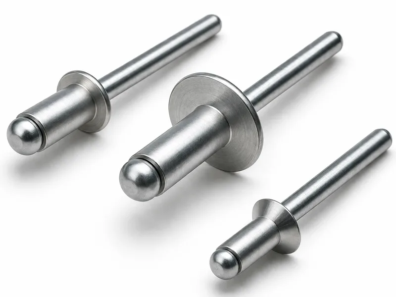
DIN 7337 break mandrel blind rivets — the classic open blind rivet with the head/grip/length ladder for d1 3,0 to 5,0 mm; superseded by DIN EN ISO 14589 (the source names it as current norm) with equivalents ISO 15983, CSN 022391 and UNI 9200.
Last updated: 2026-11
Specifications
DIN 7337 is the entry point of the blind-rivet family: a break-mandrel rivet set from one side, where pulling the mandrel expands the body and the mandrel breaks off at the head once the grip is filled. The source page itself states "Current norm: DIN EN ISO 14589" — DIN 7337 lives on as the callout factories still print on drawings, read as its ISO successor (equivalents listed: ISO 15983, CSN 022391, UNI 9200) — which is why an RFQ that names the standard explicitly, not just "4 mm blind rivets", ships the right part. The collected table is the whole sizing ladder in one grid: body diameters d1 3,0 / 3,2 / 4,0 / 4,8 / 5,0 with dome head diameters d2 6,5 to 9,5, each diameter carrying its grip bands (the column printed "length clip" — the total thickness of the sheets being clamped) against the rivet length l from 6 to 25 mm. Sizing is grip-driven: pick the band that brackets your stack-up, then read l off the same row. Materials per the Makings panel: steel, stainless A2, and non-ferrous aluminium or copper bodies — the aluminium-body/steel-mandrel build this ladder is tabulated for covers the everyday sheet-metal work; the source notes a "Steel" line separately. One reading note: at d1 4,0 the source prints two overlapping grip bands (8,5 - 12 at l=16 and 11,5 - 14 at l=18) — carried verbatim, see the anomaly FAQ before relying on the band edges there.
| Standard / scope | DIN 7337 break mandrel blind rivets (source title "DIN 7337 - Break mandrel blind rivets"); the source states "Current norm: DIN EN ISO 14589", equivalents ISO 15983; CSN 022391; UNI 9200 |
|---|---|
| Body diameters (d1) | 3,0 / 3,2 / 4,0 / 4,8 / 5,0 mm — head diameters d2 6,5 / 6,5 / 8,0 / 9,5 / 9,5 mm respectively (dome head) |
| Grip bands ("length clip") | per diameter, thinnest to thickest: 3,0 → 1 - 3 up to 8 - 12; 3,2 → 1 - 3 up to 9 - 12; 4,0 → 1 - 2,5 up to 12 - 16; 4,8 → 2 - 4 up to 11 - 15; 5,0 → 2 - 4 up to 15 - 20 (mm of clamped sheet) |
| Rivet lengths (l) | 6 to 25 mm across the ladder: 6-16 for d1 3,0/3,2, 6-20 for d1 4,0, 8-20 for d1 4,8/5,0 — grip band and length are read off the same table row |
| Materials | Steel; stainless A2; non-ferrous Aluminium, Copper per the source Makings panel; thread "-" (unthreaded rivet). The strength tables below extend this to the standard's five body materials: Al, St, A2 stainless, NiCu (nickel-alloy) and CuNi (copper-alloy) |
| Strength (tabulated below) | Minimum shear and tensile force per body material and diameter, d1 2,4 to 6,4 — DIN 7337 tables 6/7, dual-sourced (standard document + Westfield Fasteners tables agree on every cell); joint-hole nominal d3 = d1 + 0,1 per DIN 7337 table 8 |
| Not tabulated | Head-geometry tolerance rows and the per-material grip tables for the 2,4-6,4 ladder (this page's grip grid covers d1 3,0-5,0), hole-tolerance size split, countersunk-head variant — confirmed at quotation |
| d1 | d2 | length clip | l |
|---|---|---|---|
| 3,0 | 6,5 | 1 - 3 | 6 |
| 3,0 | 6,5 | 3 - 5 | 8 |
| 3,0 | 6,5 | 5 - 7 | 10 |
| 3,0 | 6,5 | 7 - 9 | 12 |
| 3,0 | 6,5 | 8 - 12 | 16 |
| 3,2 | 6,5 | 1 - 3 | 6 |
| 3,2 | 6,5 | 3 - 5 | 8 |
| 3,2 | 6,5 | 5 - 7 | 10 |
| 3,2 | 6,5 | 7 - 9 | 12 |
| 3,2 | 6,5 | 9 - 12 | 16 |
| 4,0 | 8,0 | 1 - 2,5 | 6 |
| 4,0 | 8,0 | 2,5 - 4,5 | 8 |
| 4,0 | 8,0 | 4,5 - 6,5 | 10 |
| 4,0 | 8,0 | 6,5 - 8,5 | 12 |
| 4,0 | 8,0 | 8,5 - 12 | 16 |
| 4,0 | 8,0 | 11,5 - 14 | 18 |
| 4,0 | 8,0 | 12 - 16 | 20 |
| 4,8 | 9,5 | 2 - 4 | 8 |
| 4,8 | 9,5 | 4 - 6 | 10 |
| 4,8 | 9,5 | 6 - 8 | 12 |
| 4,8 | 9,5 | 8 - 11 | 16 |
| 4,8 | 9,5 | 10 - 13 | 18 |
| 4,8 | 9,5 | 11 - 15 | 20 |
| 5,0 | 9,5 | 2 - 4 | 8 |
| 5,0 | 9,5 | 4 - 6 | 10 |
| 5,0 | 9,5 | 6 - 8 | 12 |
| 5,0 | 9,5 | 8 - 11 | 16 |
| 5,0 | 9,5 | 10 - 13 | 18 |
| 5,0 | 9,5 | 11 - 15 | 20 |
| 5,0 | 9,5 | 15 - 20 | 25 |
- "length clip" column header has no legend entry (the source legend defines d1, d2 and l only) — read as the mandrel grip band; verify against the standard document before engineering use.
- Row 17 (4,0): grip band "8,5 - 12" (l=16) overlaps the next band "11,5 - 14" (l=18) — both bands carried verbatim as printed; confirm the intended break against the standard document.
| d1 (mm) | Al body | St body | A2 body | NiCu body | CuNi body | Cu body |
|---|---|---|---|---|---|---|
| 2,4 | 300 | - | - | - | - | - |
| 3 | 500 | 800 | - | - | - | - |
| 3,2 | 600 | 1000 | 1600 | - | - | - |
| 4 | 800 | 1500 | 1800 | - | - | - |
| 4,8 | 1400 | 2400 | 2500 | 1400 | 800 | 600 |
| 5 | 1600 | 2600 | 3800 | 2000 | 1000 | 700 |
| 6 | 2500 | 3300 | 4200 | 3300 | 1500 | 1000 |
| 6,4 | 2800 | 3600 | - | - | 2300 | - |
- The vendor tables print these two rows as "Nickel Alloy" and "Copper Alloy"; the standard names the body materials NiCu and CuNi. Values agree at every shared diameter.
- The standard scan prints each material's strength ladder as a run of values without blanks, so the A2 row's five values are placed at d1 3,2-6 by consecutive alignment — the reading also reproduced by the vendor's flattened row token-for-token. Cell placement (not the values) is therefore reconstructed, and the A2 column is worth a check against the standard document for load-critical work.
- Dual-source tier (standard document + vendor specification agree on every published cell) — below the three-source verification bar; confirm load-critical applications against the standard document itself.
| d1 (mm) | Al body | St body | A2 body | NiCu body | CuNi body | Cu body |
|---|---|---|---|---|---|---|
| 2,4 | 300 | - | - | - | - | - |
| 3 | 400 | 900 | - | - | - | - |
| 3,2 | 500 | 1100 | 2000 | - | - | - |
| 4 | 800 | 2000 | 2300 | - | - | - |
| 4,8 | 1200 | 3000 | 3500 | 2000 | 900 | 700 |
| 5 | 1300 | 3200 | 4500 | 2800 | 1100 | 800 |
| 6 | 2000 | 3800 | 5000 | 3500 | 2000 | 1500 |
| 6,4 | 2100 | 4000 | - | - | 3000 | - |
- The standard scan prints the St 3 tensile value as "1 100" (typographic gap); the vendor prints 1100 — carried as 1100 on the vendor reading.
- Dual-source tier (standard document + vendor specification agree on every published cell) — below the three-source verification bar; confirm load-critical applications against the standard document itself.
| d1 (mm) | nominal hole d3 (mm) |
|---|---|
| 2,4 | 2,5 |
| 3 | 3,1 |
| 3,2 | 3,3 |
| 4 | 4,1 |
| 4,8 | 4,9 |
| 5 | 5,1 |
| 6 | 6,1 |
| 6,4 | 6,5 |
- Per-size tolerance attribution for d3 is not recoverable from either capture: the standard prints two deviation groups (+0,05/0 and +0,2/0) without a size split, and the vendor's flattened text prints an ambiguous "+0.1/0" band. Hole tolerance is therefore a quotation/standard-document item, not a tabulated value on this page.
Materials
- The Makings panel lists steel, stainless A2, and aluminium/copper as the body-material options for the family, and this grid is the steel-rivet table (its own caption reads "Dimensions steel rivets DIN 7337"). Aluminium body with steel mandrel is the volume build for sheet-metal and HVAC work; A2 stainless is the corrosion line for outdoor or food-grade enclosures; copper serves electrical earthing and decorative work. Grip band, not diameter alone, decides the part number — state the total thickness being clamped on the RFQ so the band is matched, and treat finishes (plain steel is not outdoor stock) as a quotation item.
Ordering & documentation
Documents
Shipments of DIN 7337 Break Mandrel Blind Rivets (d1 3,0 – 5,0) are backed by Mill Test Certificate (MTC), Dimensional Report, Salt Spray Test Report on request, with full batch traceability from raw material to finished product. Quality management for DIN 7337 Break Mandrel Blind Rivets (d1 3,0 – 5,0) orders follows the owner-confirmed compliance list: ISO 9001:2015, RoHS, REACH. Exact document sets are confirmed on the order.
Quotation
- The product family (DIN 7337 Break Mandrel Blind Rivets (d1 3,0 – 5,0)), product standard/designation and drawing or part number.
- The dimensions that apply to this part — such as size, pitch, length, thickness, fit, grip or groove geometry.
- Material/grade, heat-treatment condition and surface finish, together with the service environment.
- Quantity per size, delivery destination and required test or traceability documents.
Sample & supply
Minimum order quantity for din 7337 break mandrel blind rivets (d1 3,0 – 5,0) is 10,000–50,000 pieces depending on size (applies to the standard sizes and finishes for din 7337 break mandrel blind rivets (d1 3,0 – 5,0); mixed, special or custom variants are quoted — final commercial terms per quotation) Standard production for din 7337 break mandrel blind rivets (d1 3,0 – 5,0) run 10–20 days. Quantities or variants of din 7337 break mandrel blind rivets (d1 3,0 – 5,0) outside the standard range are confirmed at quotation.
Storage & shipping
DIN 7337 Break Mandrel Blind Rivets (d1 3,0 – 5,0) are packed for export and shipped factory-direct to buyers in Europe, Asia, the Americas and the Middle East. Store din 7337 break mandrel blind rivets (d1 3,0 – 5,0) dry and protected until installation, and keep coated parts in their packaging until use; specific packing and preservation requirements can be stated on the order and confirmed at quotation.
Frequently asked questions
A drawing calls DIN 7337 — is that still the right standard to order?
Yes, with one note. The source page itself states "Current norm: DIN EN ISO 14589", naming ISO 14589 as the current edition with ISO 15983, CSN 022391 and UNI 9200 as equivalents — DIN 7337 is the legacy callout the industry still prints. For the sizes in this ladder the part is the same break-mandrel blind rivet; the safe rule is to order by the drawing designation (DIN 7337 d1 x l) and, if your specification references ISO 14589, say so on the RFQ so certificate and marking paperwork matches. What you should not do is substitute a different blind-rivet family (multi-grip, structural, closed-end) because the diameter fits — grip range and head geometry differ.
How do I pick the right row — what does the "length clip" band mean?
It is the grip range: the total thickness of the sheets the rivet clamps, from the underside of the head to the point where the mandrel pulls through. Pick the row whose band brackets your stack-up (e.g. 6 mm of sheet at d1 4,0 falls in "4,5 - 6,5" at l=10), and the l value in that row is the rivet length to order. The band matters more than the diameter: the same d1 4,0 rivet at the wrong length either fails to fill the grip (loose joint) or bottoms out before the mandrel breaks (uncollapsed body). Note the header "length clip" is the source's own spelling and carries no legend entry — this page reads it as the grip band, which is the only reading consistent with the ladder; confirm against the standard document if a drawing tolerance leans on the band edges.
The d1 4,0 rows print overlapping grip bands — which band applies?
The table prints "8,5 - 12" at l=16 and then "11,5 - 14" at l=18 — the bands overlap between 8,5 and 12 mm instead of stepping cleanly. This page carries both verbatim rather than correcting them, and neither band is usable for a sizing decision at the overlap without checking the standard document: a stack-up of, say, 12 mm could read as either l=16 or l=18. The clean reading used elsewhere in the ladder (bands that share only an edge, like 2,5 - 4,5 then 4,5 - 6,5) is the intended pattern; treat the 4,0 overlap as a source transcription quirk to verify, and pick your 4,0 sizes from the unambiguous bands (1 - 2,5 through 4,5 - 6,5 and 12 - 16) where possible.
Which body material carries the load — how do I read the strength tables?
Match the weakest axis to your load. In shear, an aluminium-body rivet runs from 300 N at d1 2,4 to 2800 N at 6,4; the same diameters in steel reach 3600 N, and A2 stainless 4200 N at d1 6 — the strongest tabulated combination. In tension the gaps narrow but the order holds: A2 5000 N at d1 6 versus aluminium 1300 N. Two tabulation limits matter for selection: A2 stainless starts at d1 3,2 (tabulated through d1 6), and NiCu and Cu bodies are tabulated only for the large diameters d1 4,8 to 6; CuNi extends through d1 6,4 — there is no small-diameter NiCu rivet to choose, whatever a parts list implies. Every published value is the standard's minimum under its own test methods, not a working load: size the joint so the applied load stays well below the minimum, and treat load-critical designs as a check-against-the-standard item, since these tables are carried at a dual-source tier (standard document and vendor specification agree on every cell).
What hole should I drill for a DIN 7337 rivet?
The nominal hole runs one tenth above the rivet diameter: d1 2,4 drills 2,5 mm, 3,2 drills 3,3 mm, 4,8 drills 4,9 mm, up to 6,4 drilling 6,5 mm. Drill to that nominal and the mandrel pulls the body clean; an undersized hole prevents full seat-up, an oversized one lets the body collapse before clamp develops. The per-size tolerance split on the hole (+0,05/0 versus +0,2/0 groups) is not attributable per size from the collected sources, so treat exact hole tolerance as a standard-document or quotation item rather than reading it off this page.
What should an RFQ for DIN 7337 rivets state?
Body diameter and length (d1 x l, e.g. 4,8 x 16), the grip band or the total sheet thickness being clamped, head style (this table is the dome head; countersunk is a quotation item), body and mandrel material (aluminium/steel as the volume build, all-stainless A2 for corrosion duty, nickel-alloy or copper body for the large diameters where the strength tables offer them), finish if not plain, quantity per size — and whether your paperwork needs the ISO 14589 designation. Anything outside the tables — grip beyond this grid, geometry past d1 5,0 (the strength and hole tables cover the full 2,4-6,4 ladder, but the tabulated grip grid stops at 5,0), or structural/high-strength builds — moves to the structural and multi-grip blind-rivet lines, confirmed at quotation.
Request a Quote
Get factory-direct pricing from the manufacturer.
What to include in your DIN 7337 Break Mandrel Blind Rivets (d1 3,0 – 5,0) inquiry
- ✓ Identify blind, solid or structural rivet type and the applicable product standard.
- ✓ Give rivet-body diameter and grip range for the complete material stack, plus the prepared-hole size.
- ✓ Specify head style/clearance and state body and mandrel materials separately for blind rivets.
- ✓ For load-bearing joints, provide required rivet-specific tensile and shear values; do not substitute a bolt property class.
- ✓ State finish, quantity, destination and any lot-test or traceability documents required.
- ✓ Factory-direct pricing for your DIN 7337 Break Mandrel Blind Rivets (d1 3,0 – 5,0)
- ✓ Standard and custom specifications
- ✓ Factory-direct export to buyers in Europe, Asia, the Americas and the Middle East
- ✓ Full fastener family support