
ANSI/ASME B18.2.1 Hex Bolts (Inch Series)
ANSI/ASME B18.2.1 square and hex head bolts, inch series 1/4″–2-1/2″ — the collected per-size tables: shank d s, across-flats s (Basic/max/min), across-corners e, head height k, k w, the two-regime thread length b and fillet r.
Last updated: 2026-11
Specifications
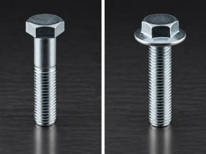
ANSI B18.2.1 is the inch-series hex bolt standard that North American drawings mean when they say "hex cap screw or hex bolt": the same head geometry family that ISO 4014 metric standardised later, running 1/4″ through 2-1/2″ in the collected tables. The head ladder is pure inch practice — across-flats printed as Basic fractions (7/16 at 1/4″ up to 3-3/4 at 2-1/2″) alongside decimal max/min — and the thread length follows a two-regime rule (b for L≤6 inches and L>6 inches of bolt length), simpler than the metric three-regime ladder because the longer standard lengths collapse into one regime. Two details worth attention when mixing with metric stock: the r fillet row is irregular in the collected source (0.025 through the small sizes, then jumps as printed at 9/16″–3/4″ — see the table footnotes), and above 2″ the b ≤6 regime is not tabulated ("/"), so the longest sizes carry the long-regime thread only. The standard pairs with inch hex nuts (ANSI B18.2.2, covered in this catalog) and SAE J429 property classes. Finishes and classes stay per RFQ.
| Standard | ANSI/ASME B18.2.1 — square and hex head bolts, inch series (hex head bolt tables) |
|---|---|
| Series | 1/4″ – 2-1/2″ (seven source column groups of three sizes each; fractions as printed, decimals in max/min) |
| Tabulated geometry | Per size: d s (max/min), s across flats (Basic fraction/max/min), e across corners (max/min), k head height (Basic/max/min), k w (min), b thread length (L≤6 / L>6 regimes, "/" above 2″ in the L≤6 regime), r fillet (max/min) |
| Inch head ladder | Across-flats Basic 7/16″ (1/4″) to 3-3/4″ (2-1/2″); head height Basic 5/32″ to 1-17/32″ — wrenching follows the fraction column, tolerances the decimals |
| Property classes / finishes | Not tabulated by the collected specification — per RFQ (typically SAE J429 grades; state grade and finish explicitly) |
| Attribute | 1/4 | 5/16 | 3/8 |
|---|---|---|---|
| d s — max | 0.25 | 0.3125 | 0.375 |
| min | 0.245 | 0.3065 | 0.369 |
| s — Basic | 7/16 | 1/2 | 9/16 |
| max | 0.438 | 0.5 | 0.562 |
| min | 0.428 | 0.489 | 0.551 |
| e — max | 0.505 | 0.577 | 0.65 |
| min | 0.488 | 0.557 | 0.628 |
| k — Basic | 5/32 | 13/64 | 15/64 |
| max | 0.163 | 0.211 | 0.243 |
| min | 0.15 | 0.195 | 0.226 |
| k w — min | 0.106 | 0.14 | 0.16 |
| b — L≤6 | 0.75 | 0.875 | 1 |
| L>6 | 1 | 1.125 | 1.25 |
| r — max | 0.025 | 0.025 | 0.025 |
| min | 0.015 | 0.015 | 0.015 |
| Attribute | 7/16 | 1/2 | 9/16 |
|---|---|---|---|
| d s — max | 0.4375 | 0.5 | 0.5625 |
| min | 0.4305 | 0.493 | 0.5545 |
| s — Basic | 5/8 | 3/4 | 13/16 |
| max | 0.625 | 0.75 | 0.812 |
| min | 0.612 | 0.736 | 0.798 |
| e — max | 0.722 | 0.866 | 0.938 |
| min | 0.698 | 0.84 | 0.91 |
| k — Basic | 9/32 | 5/16 | 23/64 |
| max | 0.291 | 0.323 | 0.371 |
| min | 0.272 | 0.302 | 0.348 |
| k w — min | 0.195 | 0.215 | 0.25 |
| b — L≤6 | 1.125 | 1.25 | 1.375 |
| L>6 | 1.375 | 1.5 | 1.625 |
| r — max | 0.025 | 0.025 | 0.45 |
| min | 0.015 | 0.015 | 0.02 |
- Row 14 (r — max): The source prints r max 0.45 at 9/16 (vs 0.025 across the small series) — reproduced verbatim as printed.
| Attribute | 5/8 | 3/4 | 7/8 |
|---|---|---|---|
| d s — max | 0.625 | 0.75 | 0.875 |
| min | 0.617 | 0.741 | 0.866 |
| s — Basic | 15/16 | 1-1/8 | 1-5/16 |
| max | 0.938 | 1.125 | 1.312 |
| min | 0.922 | 1.1 | 1.285 |
| e — max | 1.083 | 1.299 | 1.516 |
| min | 1.051 | 1.254 | 1.465 |
| k — Basic | 25/64 | 15/32 | 35/64 |
| max | 0.403 | 0.483 | 0.563 |
| min | 0.378 | 0.455 | 0.531 |
| k w — min | 0.269 | 0.324 | 0.378 |
| b — L≤6 | 1.5 | 1.75 | 2 |
| L>6 | 1.75 | 2 | 2.25 |
| r — max | 0.45 | 0.45 | 0.065 |
| min | 0.02 | 0.02 | 0.04 |
- Row 14 (r — max): The source prints r max 0.45 at 5/8 and 3/4 but 0.065 at 7/8 (min 0.04) — an irregular r ladder in the source, kept verbatim.
| Attribute | 1 | 1-1/8 | 1-1/4 |
|---|---|---|---|
| d s — max | 1 | 1.125 | 1.25 |
| min | 0.99 | 1.114 | 1.239 |
| s — Basic | 1-1/2 | 1-11/16 | 1-7/8 |
| max | 1.5 | 1.688 | 1.875 |
| min | 1.469 | 1.631 | 1.812 |
| e — max | 1.732 | 1.949 | 2.165 |
| min | 1.675 | 1.859 | 2.066 |
| k — Basic | 39/64 | 11/16 | 25/32 |
| max | 0.627 | 0.718 | 0.813 |
| min | 0.591 | 0.658 | 0.749 |
| k w — min | 0.416 | 0.461 | 0.53 |
| b — L≤6 | 2.25 | 2.5 | 2.75 |
| L>6 | 2.5 | 2.75 | 3 |
| r — max | 0.095 | 0.095 | 0.095 |
| min | 0.06 | 0.06 | 0.06 |
| Attribute | 1-3/8 | 1-1/2 | 1-3/4 |
|---|---|---|---|
| d s — max | 1.375 | 1.5 | 1.75 |
| min | 1.363 | 1.488 | 1.738 |
| s — Basic | 2-1/16 | 2-1/4 | 2-5/8 |
| max | 2.062 | 2.25 | 2.625 |
| min | 1.994 | 2.175 | 2.538 |
| e — max | 2.382 | 2.598 | 3.031 |
| min | 2.273 | 2.48 | 2.893 |
| k — Basic | 27/32 | 15/16 | 1-3/32 |
| max | 0.878 | 0.974 | 1.134 |
| min | 0.81 | 0.902 | 1.054 |
| k w — min | 0.569 | 0.64 | 0.748 |
| b — L≤6 | 3 | 3.25 | 3.75 |
| L>6 | 3.25 | 3.5 | 4 |
| r — max | 0.095 | 0.095 | 0.095 |
| min | 0.06 | 0.06 | 0.06 |
| Attribute | 2 | 2-1/4 | 2-1/2 |
|---|---|---|---|
| d s — max | 2 | 2.25 | 2.5 |
| min | 1.988 | 2.238 | 2.488 |
| s — Basic | 3 | 3-3/8 | 3-3/4 |
| max | 3 | 3.375 | 3.75 |
| min | 2.9 | 3.262 | 3.625 |
| e — max | 3.464 | 3.897 | 4.33 |
| min | 3.306 | 3.719 | 4.133 |
| k — Basic | 1-7/32 | 1-3/8 | 1-17/32 |
| max | 1.263 | 1.423 | 1.583 |
| min | 1.175 | 1.327 | 1.479 |
| k w — min | 0.825 | 0.933 | 1.042 |
| b — L≤6 | 4.25 | / | / |
| L>6 | 4.5 | 5 | 5.5 |
| r — max | 0.095 | 0.095 | 0.095 |
| min | 0.06 | 0.06 | 0.06 |
- Row 12 (b — L≤6): The source prints '/' for b at L≤6 for 2-1/4 and 2-1/2 — the regime is tabulated only for the smallest size in the table; kept verbatim.
| Attribute | 2-3/4 | 3 |
|---|---|---|
| d s — max | 2.75 | 3 |
| min | 2.738 | 2.988 |
| s — Basic | 4-1/8 | 4-1/2 |
| max | 4.125 | 4.5 |
| min | 3.988 | 4.35 |
| e — max | 4.763 | 5.196 |
| min | 4.546 | 4.959 |
| k — Basic | 1-11/16 | 1-7/8 |
| max | 1.744 | 1.935 |
| min | 1.632 | 1.815 |
| k w — min | 1.151 | 1.29 |
| b — L≤6 | / | / |
| L>6 | 6 | 6.5 |
| r — max | 0.095 | 0.095 |
| min | 0.06 | 0.06 |
- Row 12 (b — L≤6): The source prints '/' for b at L≤6 for both 2-3/4 and 3 — the regime is not tabulated at these sizes; kept verbatim.
| Nominal Screw Size | Up to 1" length | Over 1" – 2-1/2" | Over 2-1/2" – 4" | Over 4" – 6" | Longer than 6" |
|---|---|---|---|---|---|
| 1/4 – 3/8 | -.03 | -.04 | -.06 | -.10 | -.18 |
| 7/16 & 1/2 | -.03 | -.06 | -.08 | -.10 | -.18 |
| 9/16 – 3/4 | -.03 | -.08 | -.10 | -.10 | -.18 |
| 7/8 and 1 | - | -.10 | -.14 | -.16 | -.20 |
| 1-1/8 – 1-1/2 | - | -.12 | -.16 | -.18 | -.22 |
| Nominal Size | Basic Dia. | E — Body Dia. (max) | E (min) | F — Across Flats (basic) | F (max) | F (min) | G — Across Corners (max) | G (min) | H — Head Height (basic) | H (max) | H (min) | R — Fillet Radius (max) | R (min) | LT — Thread Length (≤ 6 in) | LT — Thread Length (> 6 in) |
|---|---|---|---|---|---|---|---|---|---|---|---|---|---|---|---|
| 1/4 | 0.2500 | 0.260 | 0.237 | 7/16 | 0.438 | 0.425 | 0.505 | 0.484 | 11/64 | 0.188 | 0.150 | 0.03 | 0.01 | 0.750 | 1.000 |
| 5/16 | 0.3125 | 0.324 | 0.298 | 1/2 | 0.500 | 0.484 | 0.577 | 0.552 | 7/32 | 0.235 | 0.195 | 0.03 | 0.01 | 0.875 | 1.125 |
| 3/8 | 0.3750 | 0.388 | 0.360 | 9/16 | 0.562 | 0.547 | 0.650 | 0.628 | 1/4 | 0.280 | 0.238 | 0.03 | 0.01 | 1.000 | 1.250 |
| 7/16 | 0.4375 | 0.451 | 0.423 | 5/8 | 0.625 | 0.609 | 0.722 | 0.697 | 5/16 | 0.328 | 0.275 | 0.03 | 0.01 | 1.125 | 1.375 |
| 1/2 | 0.5000 | 0.514 | 0.485 | 3/4 | 0.750 | 0.734 | 0.866 | 0.836 | 11/32 | 0.370 | 0.320 | 0.06 | 0.02 | 1.250 | 1.500 |
| 9/16 | 0.5625 | 0.577 | 0.547 | 13/16 | 0.812 | 0.796 | 0.938 | 0.904 | 3/8 | 0.420 | 0.365 | 0.06 | 0.02 | 1.375 | 1.625 |
| 5/8 | 0.6250 | 0.641 | 0.610 | 15/16 | 0.938 | 0.922 | 1.083 | 1.042 | 7/16 | 0.468 | 0.410 | 0.06 | 0.02 | 1.500 | 1.750 |
| 3/4 | 0.7500 | 0.767 | 0.734 | 1-1/8 | 1.125 | 1.094 | 1.299 | 1.249 | 17/32 | 0.530 | 0.467 | 0.09 | 0.03 | 1.750 | 2.000 |
| 7/8 | 0.8750 | 0.892 | 0.859 | 1-5/16 | 1.312 | 1.281 | 1.516 | 1.454 | 19/32 | 0.592 | 0.528 | 0.09 | 0.03 | 2.000 | 2.250 |
| 1 | 1.0000 | 1.017 | 0.984 | 1-1/2 | 1.500 | 1.469 | 1.732 | 1.661 | 21/32 | 0.655 | 0.590 | 0.09 | 0.03 | 2.250 | 2.500 |
| 1 1/8 | 1.1250 | 1.149 | 1.098 | 1-11/16 | 1.688 | 1.631 | 1.949 | 1.859 | 3/4 | 0.780 | 0.658 | 0.09 | 0.03 | 2.500 | 2.750 |
| 1 1/4 | 1.2500 | 1.274 | 1.223 | 1-7/8 | 1.875 | 1.812 | 2.165 | 2.063 | 13/16 | 0.842 | 0.720 | 0.09 | 0.03 | 2.750 | 3.000 |
| 1 3/8 | 1.3750 | 1.399 | 1.348 | 2 | 2.000 | 1.937 | 2.381 | 2.255 | 27/32 | 0.905 | 0.783 | 0.09 | 0.03 | 3.000 | 3.250 |
| 1 1/2 | 1.5000 | 1.524 | 1.473 | 2-1/4 | 2.250 | 2.187 | 2.598 | 2.464 | 29/32 | 0.967 | 0.845 | 0.12 | 0.04 | 3.250 | 3.500 |
| 1 5/8 | 1.6250 | 1.649 | 1.598 | 2-7/16 | 2.438 | 2.375 | 2.815 | 2.660 | 31/32 | 1.030 | 0.908 | 0.12 | 0.04 | 3.500 | 3.750 |
| 1 3/4 | 1.7500 | 1.774 | 1.723 | 2-5/8 | 2.625 | 2.562 | 3.031 | 2.854 | 1 1/32 | 1.092 | 0.970 | 0.12 | 0.04 | 3.750 | 4.000 |
| 1 7/8 | 1.8750 | 1.899 | 1.848 | 2-13/16 | 2.812 | 2.750 | 3.248 | 3.049 | 1 3/32 | 1.155 | 1.033 | 0.12 | 0.04 | 4.000 | 4.250 |
| 2 | 2.0000 | 2.024 | 1.973 | 3 | 3.000 | 2.937 | 3.465 | 3.236 | 1 3/16 | 1.217 | 1.095 | 0.12 | 0.04 | 4.250 | 4.500 |
| 2 1/4 | 2.2500 | 2.305 | 2.214 | 3-3/8 | 3.375 | 3.262 | 3.897 | 3.719 | 1 1/2 | 1.548 | 1.327 | 0.19 | 0.06 | 4.750 | 5.000 |
| 2 1/2 | 2.5000 | 2.555 | 2.464 | 3-3/4 | 3.750 | 3.625 | 4.330 | 4.134 | 1 5/8 | 1.717 | 1.496 | 0.19 | 0.06 | 5.250 | 5.500 |
| 2 3/4 | 2.7500 | 2.806 | 2.715 | 4-1/8 | 4.125 | 4.000 | 4.764 | 4.550 | 1 3/4 | 1.830 | 1.609 | 0.19 | 0.06 | 5.750 | 6.000 |
| 3 | 3.0000 | 3.056 | 2.965 | 4-1/2 | 4.500 | 4.375 | 5.197 | 4.965 | 1 7/8 | 1.905 | 1.684 | 0.19 | 0.06 | 6.250 | 6.500 |
| 3 1/4 | 3.2500 | 3.307 | 3.216 | 4-7/8 | 4.875 | 4.750 | 5.630 | 5.380 | 2 | 2.030 | 1.809 | 0.19 | 0.06 | 6.750 | 7.000 |
| 3 1/2 | 3.5000 | 3.557 | 3.467 | 5-1/4 | 5.250 | 5.125 | 6.063 | 5.796 | 2 1/8 | 2.155 | 1.934 | 0.19 | 0.06 | 7.250 | 7.500 |
| 3 3/4 | 3.7500 | 3.808 | 3.718 | 5-5/8 | 5.625 | 5.500 | 6.496 | 6.211 | 2 1/4 | 2.280 | 2.059 | 0.22 | 0.08 | 7.750 | 8.000 |
| 4 | 4.0000 | 4.058 | 3.968 | 6 | 6.000 | 5.875 | 6.929 | 6.627 | 2 3/8 | 2.405 | 2.184 | 0.22 | 0.08 | 8.250 | 8.500 |
- Row 1 (1/4): The source prints F basic as hyphenated fractions (1-1/8, 3-3/8, …) and splits the ladder into three groups with repeated header blocks; hyphenation is kept verbatim and duplicate headers are not reproduced as data.
Materials
- Material and property class specified per RFQ — inch hardware usually names an SAE J429 grade (2, 5, 8); confirm grade, finish and thread series (UNC/UNF) at quotation
Ordering & documentation
Documents
Shipments of ANSI/ASME B18.2.1 Hex Bolts (Inch Series) are backed by Mill Test Certificate (MTC), Dimensional Report, Salt Spray Test Report on request, with full batch traceability from raw material to finished product. Quality management for ANSI/ASME B18.2.1 Hex Bolts (Inch Series) orders follows the owner-confirmed compliance list: ISO 9001:2015, RoHS, REACH. Exact document sets are confirmed on the order.
Quotation
- The product family (ANSI/ASME B18.2.1 Hex Bolts (Inch Series)), product standard/designation and drawing or part number.
- The dimensions that apply to this part — such as size, pitch, length, thickness, fit, grip or groove geometry.
- Material/grade, heat-treatment condition and surface finish, together with the service environment.
- Quantity per size, delivery destination and required test or traceability documents.
Sample & supply
Supply source for ANSI/ASME B18.2.1 Hex Bolts (Inch Series): own manufacturing plus qualified outsourcing (per the owner-confirmed scope of supply (own production plus outsourcing)).
Minimum order quantity for ansi/asme b18.2.1 hex bolts (inch series) is 1,000–10,000 pieces depending on size (applies to the standard sizes and finishes for ansi/asme b18.2.1 hex bolts (inch series); mixed, special or custom variants are quoted — final commercial terms per quotation) Stock items for ansi/asme b18.2.1 hex bolts (inch series) run 3–7 days. High-strength and custom parts for ansi/asme b18.2.1 hex bolts (inch series) run 15–25 days. Quantities or variants of ansi/asme b18.2.1 hex bolts (inch series) outside the standard range are confirmed at quotation.
Storage & shipping
ANSI/ASME B18.2.1 Hex Bolts (Inch Series) are packed for export and shipped factory-direct to buyers in Europe, Asia, the Americas and the Middle East. Store ansi/asme b18.2.1 hex bolts (inch series) dry and protected until installation, and keep coated parts in their packaging until use; specific packing and preservation requirements can be stated on the order and confirmed at quotation.
Frequently asked questions
Metric ISO 4014 bolt into an inch-series assembly — close enough?
No — and the head is the giveaway. The collected B18.2.1 tables run in inches with their own across-flats ladder: a 1/2″-13 hex bolt carries a 3/4″ Basic across-flats, while its nearest metric neighbour M12 uses 18 mm (0.709″) — no metric wrench correctly fits an inch head, and the mix propagates to the nuts, the washer ODs and the tapped holes. Thread series makes it worse: UNC/UNF pitches do not engage metric threads beyond a destructive half-turn. Where inch hardware is genuinely needed — US-origin equipment, replacement of existing inch bolt lines, API-pattern flanges — source B18.2.1 bolts with B18.2.2 nuts and J429 grades as a matched set, and quote the fraction size plus grade ("1/2″-13 UNC, J429 Grade 5") rather than a decimal. The collected tables also flag two reading notes: the r fillet row is irregular above 7/16″ (see footnotes) and bolts longer than 2″ tabulate the L>6 thread regime only — check the thread length against your grip before ordering.
What is the MOQ and lead time for this bolt type?
The minimum order quantity for ANSI/ASME B18.2.1 Hex Bolts (Inch Series) is 1,000–10,000 pieces depending on size. Stock items of ANSI/ASME B18.2.1 Hex Bolts (Inch Series) ship in 3–7 days; high-strength and custom parts in 15–25 days. Common sizes of ANSI/ASME B18.2.1 Hex Bolts (Inch Series) are widely stocked; confirm the exact schedule against quantity and size mix at quotation.
What is the MOQ and lead time for ANSI/ASME B18.2.1 Hex Bolts (Inch Series)?
Orders under this designation have a minimum order quantity of 1,000–10,000 pieces depending on size. Stock items ship in 3–7 days; high-strength and custom parts in 15–25 days. Final commercial terms are confirmed per quotation.
What should an RFQ for ANSI/ASME B18.2.1 Hex Bolts (Inch Series) state?
State the full designation (ANSI/ASME B18.2.1), thread size and pitch or diameter, length or head dimension, finish, quantity per size, plus the destination country and any required certificate such as a mill test report per EN 10204 3.1; dimensions and schedule for this designation are confirmed with the quotation.
Related knowledge
- What Bolt Property Classes 8.8, 10.9 and 12.9 Encode — and When High Strength Stops Being the Right Choice
- Bolt Grade Selection: ISO 898-1 8.8/10.9/12.9 vs ASTM A307 and A325
- 8.8 vs 10.9 vs 12.9 Bolts: Strength, Hardness and Cost — What the Evidence Settles
- Calculating Bolt Preload and Clamp Force: Torque, Friction and Tightening Method
- How to Determine Tightening Torque and Choose a Tightening Method for a Bolted Joint
- Fastener Failure Modes: Which Fatigue, Creep and SCC Controls the Evidence Supports
- Hydrogen Embrittlement in High-Strength Bolts: Which Grades Need Controls, Which Coatings and Baking Schedules Are Acceptable, and What to Require Before the RFQ
Request a Quote
Get factory-direct pricing from the manufacturer.
What to include in your ANSI/ASME B18.2.1 Hex Bolts (Inch Series) inquiry
- ✓ Name the bolt standard and product form, then give nominal diameter, pitch, length and threaded length.
- ✓ State the applicable property class or material grade, head style, and coating or finish.
- ✓ Identify the mating nut/washer and the joint duty; include any specified preload, tightening method or friction condition.
- ✓ Give quantity per size, destination and required material or inspection certificates.
- ✓ Factory-direct pricing for your ANSI/ASME B18.2.1 Hex Bolts (Inch Series)
- ✓ Standard and custom specifications
- ✓ Factory-direct export to buyers in Europe, Asia, the Americas and the Middle East
- ✓ Full fastener family support