
ASME B18.2.3.4M Hex Flange Screws (Metric)
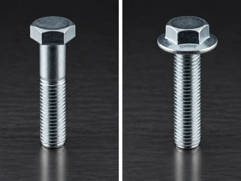
Metric hex flange screws per ASME B18.2.3.4M — flanged-head dimension table for M5 to M16: body diameter, width across flats/corners, flange diameter Dc, bearing circle Dw, flange edge thickness C, head height K, wrenching height K1, fillet radius R.
Last updated: 2026-11
Specifications
B18.2.3.4M integrates a flange under the hex head, and the collected table (M5 - M16, coarse metric pitches) reads as a study in what the flange does: flange diameter Dc max runs 11.4 mm at M5 up to 32.8 at M16, with a bearing circle Dw min (9.4 at M5, 30.1 at M16) that spreads the clamp load over the joint without a separate washer — one part fewer to stock and one alignment step fewer to get wrong. The flange edge thickness C min (1 at M5 rising to 2.4 at M16) is the thin rim that must survive tightening without cracking, which is why the small-end sizes matter when sourcing: an underspecified C is the classic failure of a cheap flange screw. Across flats follows the standard metric hex ladder (7 at M5, 10 at M8, 13 at M10, 15 at M12, 21 at M16); head height K max (5.6 at M5 to 15.1 at M16) and wrenching height K1 stay proportionate. The trailing footnote row cites ASME B18.2.3.4M-1984 and defines the transition thread x as a calculation dimension. Strength classes and finish are not tabulated — per RFQ.
| Standard | ASME B18.2.3.4M — metric hex flange screws, coarse pitch, sizes M5 - M16 (M5 x 0.8 through M16 x 2) |
|---|---|
| Flange geometry | Flange diameter Dc max (M5: 11.4; M8: 17; M12: 24.7; M16: 32.8), bearing circle Dw min (M5: 9.4; M12: 22; M16: 30.1), flange edge thickness C min (M5: 1; M16: 2.4) — washer-face function built into the head |
| Width across flats S | Max/min as printed (M5: 7/6.64; M8: 10/9.64; M10: 13/12.57; M12: 15/14.57; M16: 21/20.57) — note the ladder diverges from the ISO hex ladder at M10 and above (ISO 4017 M10: 16, M12: 18), so check socket stock |
| Head height K | Max/min (M5: 5.6/-; M8: 8.5/-; M12: 11.9/-; M16: 15.1/-), wrenching height K1 min (M5: 2.3; M8: 3.8; M16: 6.7) |
| Body diameter Ds | Max = nominal, min for rolling (M5: 4.82; M8: 7.78; M16: 15.73) |
| Fillet radius R | Max tabulated per size (0.3 at M5 rising through the ladder) — the under-head fillet that the flange widens |
| Not tabulated | Strength classes, proof loads, thread lengths B, finish — per RFQ |
| Nominal Dia., D, and Thread Pitch | Body Dia., Ds | Body Dia., Ds | Width Across Flats, S | Width Across Flats, S | Width Across Corners, E | Width Across Corners, E | Flange Dia., Dc | Bearing Circle Dia., Dw | Flange Edge Thickness, C | Head Height, K | Wrenching Height, K1 | Fillet Radius, R |
|---|---|---|---|---|---|---|---|---|---|---|---|---|
| Nominal Dia., D, and Thread Pitch | Max | Min | Max | Min | Max | Min | Max | Min | Min | Max | Min | Max |
| ANSI B18.2.3.4M - M5 × 0.8 | 5 | 4.82 | 7 | 6.64 | 8.08 | 7.44 | 11.4 | 9.4 | 1 | 5.6 | 2.3 | 0.3 |
| ANSI B18.2.3.4M - M6 × 1 | 6 | 5.82 | 8 | 7.64 | 9.24 | 8.56 | 13.6 | 11.6 | 1.1 | 6.8 | 2.9 | 0.4 |
| ANSI B18.2.3.4M - M8 × 1.25 | 8 | 7.78 | 10 | 9.64 | 11.55 | 10.8 | 17 | 14.9 | 1.2 | 8.5 | 3.8 | 0.5 |
| ANSI B18.2.3.4M - M10 × 1.5 | 10 | 9.78 | 13 | 12.57 | 15.01 | 14.08 | 20.8 | 18.7 | 1.5 | 9.7 | 4.3 | 0.6 |
| ANSI B18.2.3.4M - M12 × 1.75 | 12 | 11.73 | 15 | 14.57 | 17.32 | 16.32 | 24.7 | 22 | 1.8 | 11.9 | 5.4 | 0.7 |
| ANSI B18.2.3.4M - M14 × 2 | 14 | 13.73 | 18 | 17.57 | 20.78 | 19.68 | 28.6 | 25.9 | 2.1 | 12.9 | 5.6 | 0.8 |
| ANSI B18.2.3.4M - M16 × 2 | 16 | 15.73 | 21 | 20.48 | 24.25 | 22.94 | 32.8 | 30.1 | 2.4 | 15.1 | 6.7 | 1 |
| All dimensions are in millimeters. Basic thread lengths, B, are the same as given in. Transition thread length, x, includes the length of incomplete threads and tolerances on grip gaging length and body length. This dimension is intended for calculation purposes only. For additional manufacturing and acceptance specifications, reference should be made to ASME B18.2.3.4M-1984 standard. | All dimensions are in millimeters. Basic thread lengths, B, are the same as given in. Transition thread length, x, includes the length of incomplete threads and tolerances on grip gaging length and body length. This dimension is intended for calculation purposes only. For additional manufacturing and acceptance specifications, reference should be made to ASME B18.2.3.4M-1984 standard. | All dimensions are in millimeters. Basic thread lengths, B, are the same as given in. Transition thread length, x, includes the length of incomplete threads and tolerances on grip gaging length and body length. This dimension is intended for calculation purposes only. For additional manufacturing and acceptance specifications, reference should be made to ASME B18.2.3.4M-1984 standard. | All dimensions are in millimeters. Basic thread lengths, B, are the same as given in. Transition thread length, x, includes the length of incomplete threads and tolerances on grip gaging length and body length. This dimension is intended for calculation purposes only. For additional manufacturing and acceptance specifications, reference should be made to ASME B18.2.3.4M-1984 standard. | All dimensions are in millimeters. Basic thread lengths, B, are the same as given in. Transition thread length, x, includes the length of incomplete threads and tolerances on grip gaging length and body length. This dimension is intended for calculation purposes only. For additional manufacturing and acceptance specifications, reference should be made to ASME B18.2.3.4M-1984 standard. | All dimensions are in millimeters. Basic thread lengths, B, are the same as given in. Transition thread length, x, includes the length of incomplete threads and tolerances on grip gaging length and body length. This dimension is intended for calculation purposes only. For additional manufacturing and acceptance specifications, reference should be made to ASME B18.2.3.4M-1984 standard. | All dimensions are in millimeters. Basic thread lengths, B, are the same as given in. Transition thread length, x, includes the length of incomplete threads and tolerances on grip gaging length and body length. This dimension is intended for calculation purposes only. For additional manufacturing and acceptance specifications, reference should be made to ASME B18.2.3.4M-1984 standard. | All dimensions are in millimeters. Basic thread lengths, B, are the same as given in. Transition thread length, x, includes the length of incomplete threads and tolerances on grip gaging length and body length. This dimension is intended for calculation purposes only. For additional manufacturing and acceptance specifications, reference should be made to ASME B18.2.3.4M-1984 standard. | All dimensions are in millimeters. Basic thread lengths, B, are the same as given in. Transition thread length, x, includes the length of incomplete threads and tolerances on grip gaging length and body length. This dimension is intended for calculation purposes only. For additional manufacturing and acceptance specifications, reference should be made to ASME B18.2.3.4M-1984 standard. | All dimensions are in millimeters. Basic thread lengths, B, are the same as given in. Transition thread length, x, includes the length of incomplete threads and tolerances on grip gaging length and body length. This dimension is intended for calculation purposes only. For additional manufacturing and acceptance specifications, reference should be made to ASME B18.2.3.4M-1984 standard. | All dimensions are in millimeters. Basic thread lengths, B, are the same as given in. Transition thread length, x, includes the length of incomplete threads and tolerances on grip gaging length and body length. This dimension is intended for calculation purposes only. For additional manufacturing and acceptance specifications, reference should be made to ASME B18.2.3.4M-1984 standard. | All dimensions are in millimeters. Basic thread lengths, B, are the same as given in. Transition thread length, x, includes the length of incomplete threads and tolerances on grip gaging length and body length. This dimension is intended for calculation purposes only. For additional manufacturing and acceptance specifications, reference should be made to ASME B18.2.3.4M-1984 standard. | All dimensions are in millimeters. Basic thread lengths, B, are the same as given in. Transition thread length, x, includes the length of incomplete threads and tolerances on grip gaging length and body length. This dimension is intended for calculation purposes only. For additional manufacturing and acceptance specifications, reference should be made to ASME B18.2.3.4M-1984 standard. |
- The trailing row repeats the source's usage note in every column, carried verbatim (it cites ASME B18.2.3.4M-1984).
Materials
- Metric hex flange screws ship in carbon steel by property class (8.8 / 10.9 typical for flanged heads) and stainless A2/A4; the flange geometry tabulated here is material-independent. Flanged heads crack at the edge thickness C if over-torqued in hard joints — state the property class and joint type on the RFQ
Ordering & documentation
Documents
Shipments of ASME B18.2.3.4M Hex Flange Screws (Metric) are backed by Mill Test Certificate (MTC), Dimensional Report, Salt Spray Test Report on request, with full batch traceability from raw material to finished product. Quality management for ASME B18.2.3.4M Hex Flange Screws (Metric) orders follows the owner-confirmed compliance list: ISO 9001:2015, RoHS, REACH. Exact document sets are confirmed on the order.
Quotation
- The product family (ASME B18.2.3.4M Hex Flange Screws (Metric)), product standard/designation and drawing or part number.
- The dimensions that apply to this part — such as size, pitch, length, thickness, fit, grip or groove geometry.
- Material/grade, heat-treatment condition and surface finish, together with the service environment.
- Quantity per size, delivery destination and required test or traceability documents.
Sample & supply
Supply source for ASME B18.2.3.4M Hex Flange Screws (Metric): own manufacturing plus qualified outsourcing (per the owner-confirmed scope of supply (own production plus outsourcing)).
Minimum order quantity for asme b18.2.3.4m hex flange screws (metric) is 1,000–10,000 pieces depending on size (applies to the standard sizes and finishes for asme b18.2.3.4m hex flange screws (metric); mixed, special or custom variants are quoted — final commercial terms per quotation) Stock items for asme b18.2.3.4m hex flange screws (metric) run 3–7 days. High-strength and custom parts for asme b18.2.3.4m hex flange screws (metric) run 15–25 days. Quantities or variants of asme b18.2.3.4m hex flange screws (metric) outside the standard range are confirmed at quotation.
Storage & shipping
ASME B18.2.3.4M Hex Flange Screws (Metric) are packed for export and shipped factory-direct to buyers in Europe, Asia, the Americas and the Middle East. Store asme b18.2.3.4m hex flange screws (metric) dry and protected until installation, and keep coated parts in their packaging until use; specific packing and preservation requirements can be stated on the order and confirmed at quotation.
Frequently asked questions
Flange screw or bolt-plus-washer — when is the integrated flange the better call?
When assembly count and alignment drive the cost. The collected table shows the flange doing the washer's job by geometry: a bearing circle Dw of 22 mm at M12 spreads the clamp load without a loose washer that can be omitted, installed upside down, or wander on automated lines. The trade-offs are the ones the dimensions imply: the bearing diameter is fixed at the flange size — you cannot upsize it for soft materials the way you would stack a fender washer, and the flange edge thickness C (1 - 2.4 mm across the ladder) is a stress-raiser if the head is pulled square against an unflat surface. For high-volume assembly and sheet-metal or moderately flat joints the flange wins; for soft or misaligned joints, bolt plus a properly sized washer still earns its extra part.
What does the 1984 footnote in the table refer to?
The collected page's trailing note anchors the table to ASME B18.2.3.4M-1984 and defines two reading rules worth carrying into any RFQ: thread lengths B are "the same as given in" the base standard (they are not reproduced in this table), and the transition thread length x — the run of incomplete threads — is a calculation dimension only, not an inspection measurement. In buying terms: confirm the grip and thread length you need explicitly, because the flange table governs head and bearing geometry, not how far the thread runs down the shank.
What is the MOQ and lead time for ASME B18.2.3.4M Hex Flange Screws (Metric)?
Orders under this designation have a minimum order quantity of 1,000–10,000 pieces depending on size. Stock items ship in 3–7 days; high-strength and custom parts in 15–25 days. Final commercial terms are confirmed per quotation.
What should an RFQ for ASME B18.2.3.4M Hex Flange Screws (Metric) state?
State the full designation (ASME B18.2.3.4M), thread size and pitch or diameter, length or head dimension, finish, quantity per size, plus the destination country and any required certificate such as a mill test report per EN 10204 3.1; dimensions and schedule for this designation are confirmed with the quotation.
Related knowledge
- What Bolt Property Classes 8.8, 10.9 and 12.9 Encode — and When High Strength Stops Being the Right Choice
- Bolt Grade Selection: ISO 898-1 8.8/10.9/12.9 vs ASTM A307 and A325
- 8.8 vs 10.9 vs 12.9 Bolts: Strength, Hardness and Cost — What the Evidence Settles
- Calculating Bolt Preload and Clamp Force: Torque, Friction and Tightening Method
- How to Determine Tightening Torque and Choose a Tightening Method for a Bolted Joint
- Fastener Failure Modes: Which Fatigue, Creep and SCC Controls the Evidence Supports
- Hydrogen Embrittlement in High-Strength Bolts: Which Grades Need Controls, Which Coatings and Baking Schedules Are Acceptable, and What to Require Before the RFQ
Request a Quote
Get factory-direct pricing from the manufacturer.
What to include in your ASME B18.2.3.4M Hex Flange Screws (Metric) inquiry
- ✓ Name the bolt standard and product form, then give nominal diameter, pitch, length and threaded length.
- ✓ State the applicable property class or material grade, head style, and coating or finish.
- ✓ Identify the mating nut/washer and the joint duty; include any specified preload, tightening method or friction condition.
- ✓ Give quantity per size, destination and required material or inspection certificates.
- ✓ Factory-direct pricing for your ASME B18.2.3.4M Hex Flange Screws (Metric)
- ✓ Standard and custom specifications
- ✓ Factory-direct export to buyers in Europe, Asia, the Americas and the Middle East
- ✓ Full fastener family support