
ANSI/ASME B18.6.1 Wood Screws (Inch Series)
Wood screws to ANSI/ASME B18.6.1, inch series #0–#24 — gimlet-point thread-forming screws in flat, round and oval head patterns, with the collected per-size tables: head diameters and heights, slot and driver-recess dimensions, thread and body diameters for cut and rolled thread, and the extended #0–#24 ladder.
Last updated: 2026-11
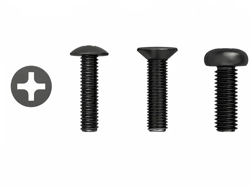
Specifications
A wood screw to B18.6.1 is a thread-forming fastener with a gimlet point and a sharp-crested coarse-pitch thread: it cuts its own mating thread when driven into wood and other resilient materials, so no tapped hole or nut is needed on the joint. The designation spans two thread-forming variants the collected tables separate — cut thread screws, whose shank tapers toward the point, and rolled thread screws, whose body diameter stays constant — and the thread-length rules differ with them: roughly two-thirds of the nominal screw length for cut thread, and at least four times the basic screw diameter (or two-thirds of nominal, whichever is greater) for rolled thread, with screws too short for that minimum threaded as close to the head as practicable. The tables on this page carry the three common head patterns — flat (countersunk), round and oval — with per-size head diameter and height, slot width and depth, and the Phillips recess dimensions (driver size included, #1–#3 by screw size); a second published ladder extends the size range to #0 and #24, sizes the first table does not carry. Where the published tables overlap (#2–#16) the values agree — they are independent captures of the same standard. Driver selection is tabulated, not guessed: a #2 wood screw takes a #1 Phillips bit, #5–#9 take #2, and #10 and up take #3. Screws #14 and larger carry proportionally deeper slots and larger recesses — check the table rather than assuming the bit size scales linearly.
| Pattern | Gimlet-point thread-forming wood screw, inch series to ANSI/ASME B18.6.1 — cut thread (tapered shank) or rolled thread (constant body diameter), slotted or Phillips drive |
|---|---|
| Size range | #2–#16 per the flat/round/oval head tables and the thread & body table; #0, #1, #18, #20 and #24 per the second collected ladder — #3 is absent from the round-head table (source gap) |
| Tabulated geometry | Per size and head pattern: head diameter (max/min), head height, slot width and depth (max/min), Phillips recess dia./depth/width with driver size; thread: major diameter, TPI (26 at #2 down to 7 at #24), body diameter for cut and rolled thread, thread depth |
| Thread length rule | Cut thread: ~2/3 of nominal screw length. Rolled thread: at least 4× basic screw diameter or 2/3 nominal (whichever greater); shorter screws threaded to the underside of the head as practicable |
| Material | Source names carbon steel as the standard material; finishes, hardness and corrosion protection per RFQ (state the exposure environment with the order) |
| Nominal Size | Phillips Driver Size | Head Dia. (A) Max | A Min | Head Height (H) Ref | Width of Slot (J) Max | J Min | Depth of Slot (T) Max | T Min | Recess Dia. Max (M) | Recess Dia. Min (M) | Recess Depth Max (G) | Recess Depth Min (G) | Recess Width Min (N) |
|---|---|---|---|---|---|---|---|---|---|---|---|---|---|
| 2 | 1 | .172 | .147 | .051 | .031 | .023 | .023 | .015 | .102 | .089 | .063 | .047 | .017 |
| 3 | 1 | .199 | .141 | .059 | .035 | .027 | .027 | .017 | .107 | .094 | .068 | .052 | .018 |
| 4 | 1 | .225 | .195 | .067 | .039 | .031 | .030 | .020 | .128 | .115 | .089 | .073 | .018 |
| 5 | 2 | .252 | .220 | .075 | .043 | .035 | .034 | .022 | .154 | .141 | .086 | .063 | .027 |
| 6 | 2 | .279 | .244 | .083 | .048 | .039 | .038 | .024 | .174 | .161 | .106 | .083 | .029 |
| 7 | 2 | .305 | .268 | .091 | .048 | .039 | .041 | .027 | .189 | .176 | .121 | .098 | .030 |
| 8 | 2 | .332 | .292 | .100 | .054 | .045 | .045 | .029 | .204 | .191 | .136 | .113 | .032 |
| 9 | 2 | .358 | .316 | .108 | .054 | .045 | .049 | .032 | .214 | .201 | .146 | .123 | .033 |
| 10 | 3 | .385 | .340 | .116 | .060 | .050 | .053 | .034 | .258 | .245 | .146 | .123 | .034 |
| 12 | 3 | .438 | .389 | .132 | .067 | .056 | .060 | .039 | .283 | .270 | .171 | .148 | .036 |
| 14 | 3 | .507 | .452 | .153 | .075 | .064 | .070 | .046 | .283 | .270 | .171 | .148 | .036 |
| 16 | 3 | .544 | .485 | .164 | .075 | .064 | .075 | .049 | .303 | .290 | .191 | .168 | .039 |
- Row 10 (12): The #12 and #14 rows print identical recess values (M .283/.270, G .171/.148, N .036) in the source — reproduced verbatim.
| Nominal Size | Phillips Driver Size | Head Dia. (A) Max | A Min | Head Height (H) Max | H Min | Width of Slot (J) Max | J Min | Depth of Slot (T) Max | T Min | Recess Dia. Max (M) | Recess Dia. Min (M) | Recess Depth Max (G) | Recess Depth Min (G) | Recess Width Min (N) |
|---|---|---|---|---|---|---|---|---|---|---|---|---|---|---|
| 2 | 1 | .162 | .146 | .069 | .059 | .031 | .023 | .048 | .037 | .114 | .101 | .064 | .042 | .018 |
| 4 | 2 | .211 | .193 | .086 | .075 | .039 | .031 | .058 | .044 | .130 | .117 | .083 | .063 | .019 |
| 5 | 2 | .236 | .217 | .095 | .083 | .043 | .035 | .063 | .047 | .154 | .141 | .074 | .046 | .027 |
| 6 | 2 | .260 | .240 | .103 | .091 | .048 | .039 | .068 | .051 | .162 | .149 | .084 | .056 | .027 |
| 7 | 2 | .285 | .264 | .111 | .099 | .048 | .039 | .072 | .055 | .170 | .157 | .092 | .066 | .028 |
| 8 | 2 | .309 | .287 | .120 | .107 | .054 | .045 | .077 | .058 | .178 | .165 | .101 | .075 | .030 |
| 9 | 2 | .334 | .311 | .128 | .115 | .054 | .045 | .082 | .062 | .186 | .173 | .110 | .084 | .030 |
| 10 | 2 | .359 | .334 | .137 | .123 | .060 | .050 | .087 | .065 | .195 | .182 | .119 | .093 | .031 |
| 12 | 3 | .408 | .382 | .153 | .139 | .067 | .056 | .096 | .073 | .249 | .236 | .125 | .099 | .032 |
| 14n | 3 | .457 | .429 | .170 | .155 | .075 | .064 | .106 | .080 | .265 | .252 | .142 | .116 | .034 |
- Row 10 (14n): The final size prints "14n" in the source (the "n" suffix token is not explained on the page) — reproduced verbatim. The round-head ladder skips #3; absence is a source gap, not evidence the size does not exist.
| Nominal Size | Phillips Driver Size | Head Dia. (A) Max | A Min | Side Height (H) Ref | Total Height Max | Total Height Min | Width of Slot (J) Max | J Min | Depth of Slot (T) Max | T Min | Recess Dia. Max (M) | Recess Dia. Min (M) | Recess Depth Max (G) | Recess Depth Min (G) | Recess Width Min (N) |
|---|---|---|---|---|---|---|---|---|---|---|---|---|---|---|---|
| 4 | 1 | .225 | .195 | .067 | .104 | .084 | .039 | .031 | .059 | .049 | .136 | .123 | .094 | .077 | .019 |
| 5 | 2 | .252 | .220 | .075 | .116 | .095 | .043 | .035 | .067 | .055 | .158 | .145 | .085 | .061 | .028 |
| 6 | 2 | .279 | .244 | .083 | .128 | .105 | .048 | .039 | .074 | .060 | .178 | .165 | .105 | .080 | .030 |
| 8 | 2 | .332 | .292 | .100 | .152 | .126 | .054 | .045 | .088 | .072 | .205 | .192 | .131 | .106 | .033 |
| 9 | 2 | .358 | .316 | .108 | .164 | .137 | .054 | .045 | .095 | .078 | .216 | .203 | .144 | .119 | .034 |
| 10 | 3 | .385 | .340 | .116 | .176 | .148 | .060 | .050 | .103 | .084 | .261 | .248 | .142 | .118 | .037 |
| 12 | 3 | .438 | .389 | .132 | .200 | .169 | .067 | .056 | .117 | .096 | .283 | .270 | .165 | .140 | .040 |
| Nominal Size | Basic Screw Dia. | Threads Per Inch | Major Thread Dia. (D) Max | D Min | Body Dia. (E) Cut Thread Max | E Cut Min | Body Dia. (E) Rolled Thread Max | E Rolled Min | Thread Depth (F) Min |
|---|---|---|---|---|---|---|---|---|---|
| 2 | .086 | 26 | .090 | .079 | .090 | .079 | .075 | .064 | .010 |
| 3 | .099 | 24 | .103 | .092 | .103 | .092 | .086 | .075 | .014 |
| 4 | .112 | 22 | .116 | .105 | .116 | .105 | .095 | .084 | .016 |
| 5 | .125 | 20 | .129 | .118 | .129 | .118 | .107 | .096 | .018 |
| 6 | .138 | 18 | .142 | .131 | .142 | .131 | .118 | .107 | .020 |
| 7 | .151 | 16 | .155 | .144 | .155 | .144 | .127 | .116 | .022 |
| 8 | .164 | 15 | .168 | .157 | .168 | .157 | .136 | .125 | .023 |
| 9 | .177 | 14 | .181 | .170 | .181 | .170 | .147 | .136 | .026 |
| 10 | .190 | 13 | .194 | .183 | .194 | .183 | .157 | .146 | .030 |
| 12 | .216 | 11 | .220 | .209 | .220 | .209 | .176 | .165 | .031 |
| 14 | .242 | 10 | .246 | .235 | .246 | .235 | .201 | .190 | .035 |
| 16 | .268 | 9 | .272 | .261 | .272 | .261 | .214 | .203 | .038 |
| Nom. Size | Threads Per Inch | Basic Dia. of Screw (Da) | Width of Slot (J) Max, Sharp Edge | J Min, Edge Rounded or Flat | Head Dia. (A) Max | A Min | Head Dia. (B) Max | B Min | Head Radius (P) Max | Height of Head (H) Ref |
|---|---|---|---|---|---|---|---|---|---|---|
| 0 | 32 | .060 | .023 | .016 | .119 | .099 | .116 | .104 | .020 | .035 |
| 1 | 28 | .073 | .026 | .019 | .146 | .123 | .142 | .130 | .025 | .043 |
| 2 | 26 | .086 | .031 | .023 | .172 | .147 | .167 | .155 | .035 | .051 |
| 3 | 24 | .099 | .035 | .027 | .199 | .171 | .193 | .180 | .037 | .059 |
| 4 | 22 | .112 | .039 | .031 | .225 | .195 | .219 | .205 | .042 | .067 |
| 5 | 20 | .125 | .043 | .035 | .252 | .220 | .245 | .231 | .044 | .075 |
| 6 | 18 | .138 | .048 | .039 | .279 | .244 | .270 | .256 | .046 | .083 |
| 7 | 16 | .151 | .048 | .039 | .305 | .268 | .296 | .281 | .049 | .091 |
| 8 | 15 | .164 | .054 | .045 | .332 | .292 | .322 | .306 | .052 | .100 |
| 9 | 14 | .177 | .054 | .045 | .358 | .316 | .348 | .331 | .056 | .108 |
| 10 | 13 | .190 | .060 | .050 | .385 | .340 | .373 | .357 | .061 | .116 |
| 12 | 11 | .216 | .067 | .056 | .438 | .389 | .425 | .407 | .078 | .132 |
| 14 | 10 | .242 | .075 | .064 | .507 | .452 | .492 | .473 | .087 | .153 |
| 16 | 9 | .268 | .075 | .064 | .544 | .485 | .528 | .508 | .094 | .164 |
| 18 | 8 | .294 | .084 | .072 | .635 | .568 | .615 | .594 | .099 | .191 |
| 20 | 8 | .320 | .084 | .072 | .650 | .582 | .631 | .608 | .121 | .196 |
| 24 | 7 | .372 | .094 | .081 | .762 | .685 | .740 | .716 | .143 | .230 |
- Row 2 (1): The #7 row prints the same J pair (.048/.039) as #6 — reproduced verbatim. Overlapping sizes (#2–#16) agree across the published tables on this page, which are independent captures.
| Nominal Size | Threads Per Inch | Total Height of Head (O) Max | O Min | Height of Head (K) Max | K Min | Depth of Slot (T) Max | T Min | Depth of Slot (U) Max | U Min | Depth of Slot (V) Max | V Min |
|---|---|---|---|---|---|---|---|---|---|---|---|
| 0 | 32 | .056 | .041 | .039 | .031 | .015 | .010 | .022 | .014 | .030 | .025 |
| 1 | 28 | .068 | .052 | .046 | .038 | .019 | .012 | .027 | .018 | .038 | .031 |
| 2 | 26 | .080 | .063 | .053 | .045 | .023 | .015 | .031 | .022 | .045 | .037 |
| 3 | 24 | .092 | .073 | .060 | .051 | .027 | .017 | .035 | .027 | .052 | .043 |
| 4 | 22 | .104 | .084 | .068 | .058 | .030 | .020 | .040 | .030 | .059 | .049 |
| 5 | 20 | .116 | .095 | .075 | .065 | .034 | .022 | .045 | .034 | .067 | .055 |
| 6 | 18 | .128 | .105 | .082 | .072 | .038 | .024 | .050 | .037 | .074 | .060 |
| 7 | 16 | .140 | .116 | .089 | .079 | .041 | .027 | .054 | .041 | .081 | .066 |
| 8 | 15 | .152 | .126 | .096 | .085 | .045 | .029 | .058 | .045 | .088 | .072 |
| 9 | 14 | .164 | .137 | .103 | .092 | .049 | .032 | .063 | .049 | .095 | .078 |
| 10 | 13 | .176 | .148 | .110 | .099 | .053 | .034 | .068 | .053 | .103 | .084 |
| 12 | 11 | .200 | .169 | .125 | .112 | .060 | .039 | .077 | .061 | .117 | .096 |
| 14 | 10 | .232 | .197 | .144 | .130 | .070 | .046 | .087 | .070 | .136 | .112 |
| 16 | 9 | .248 | .212 | .153 | .139 | .075 | .049 | .093 | .074 | .146 | .120 |
| 18 | 8 | .290 | .249 | .178 | .162 | .083 | .054 | .106 | .085 | .171 | .141 |
| 20 | 8 | .296 | .254 | .182 | .166 | .090 | .059 | .108 | .087 | .175 | .144 |
| 24 | 7 | .347 | .300 | .212 | .195 | .106 | .070 | .124 | .100 | .204 | .168 |
- Row 1 (0): The T/U/V slot-depth groups carry no per-pattern legend — they are rendered as lettered columns only, reproduced verbatim; match the group to the head pattern in the head-drawing references before quoting a specific slot depth.
Materials
- Carbon steel per the collected specification; finishes and corrosion protection specified per RFQ — name the exposure (interior dry, exterior, treated lumber) so the coating can be quoted against the application
Ordering & documentation
Documents
Shipments of ANSI/ASME B18.6.1 Wood Screws (Inch Series) are backed by Mill Test Certificate (MTC), Dimensional Report, Salt Spray Test Report on request, with full batch traceability from raw material to finished product. Quality management for ANSI/ASME B18.6.1 Wood Screws (Inch Series) orders follows the owner-confirmed compliance list: ISO 9001:2015, RoHS, REACH. Exact document sets are confirmed on the order.
Quotation
- The product family (ANSI/ASME B18.6.1 Wood Screws (Inch Series)), product standard/designation and drawing or part number.
- The dimensions that apply to this part — such as size, pitch, length, thickness, fit, grip or groove geometry.
- Material/grade, heat-treatment condition and surface finish, together with the service environment.
- Quantity per size, delivery destination and required test or traceability documents.
Sample & supply
Minimum order quantity for ansi/asme b18.6.1 wood screws (inch series) is 10,000 pieces (applies to the standard sizes and finishes for ansi/asme b18.6.1 wood screws (inch series); mixed, special or custom variants are quoted — final commercial terms per quotation) Stock items for ansi/asme b18.6.1 wood screws (inch series) run 3–7 days. Quantities or variants of ansi/asme b18.6.1 wood screws (inch series) outside the standard range are confirmed at quotation.
Storage & shipping
ANSI/ASME B18.6.1 Wood Screws (Inch Series) are packed for export and shipped factory-direct to buyers in Europe, Asia, the Americas and the Middle East. Store ansi/asme b18.6.1 wood screws (inch series) dry and protected until installation, and keep coated parts in their packaging until use; specific packing and preservation requirements can be stated on the order and confirmed at quotation.
Frequently asked questions
How do I choose between flat, round and oval head patterns, and which driver does each size take?
Choose by seating geometry, not preference. The flat head (countersunk) sits flush or below the wood surface — the collected table gives head diameter A (.225/.195 at #4 up to .544/.485 at #16) so the mating countersink or the screw's own cone can be sized; use it where a protruding head would foul sliding parts or finish surfaces. The round head sits proud on the surface and carries the largest bearing diameter for its size at the shallowest height — the choice for thin material where countersinking would weaken the joint, and for applications where the head is deliberately visible. The oval head blends both: countersunk like a flat head but with a rounded top that leaves no sharp edge — the collected table carries its side height and total height separately for exactly that trim reason. Driver size is tabulated per size rather than estimated: #2–#4 take a #1 Phillips bit, #5–#9 take #2, #10 and up take #3 in the flat and oval tables (the round-head table shifts #10 to #2 — read the table for the specific pattern you order, and note the #12/#14 flat-head rows share identical recess dimensions in the source). One gap to quote honestly: the round-head ladder in the collected data ends at "14n" and skips #3 — quote those sizes at RFQ rather than reading them off the table.
Cut thread or rolled thread — does the difference matter for my joint?
Yes, in two measurable ways the tables capture. Body diameter: the cut-thread table column and rolled-thread column differ at every size — rolled-thread body diameter is consistently smaller (for example .075/.064 at #2 against .090/.079 cut, .214/.203 at #16 against .272/.261). The cut-thread shank tapers toward the point while the rolled shank is constant-diameter, which is why the rolled body sits inside the thread envelope. Thread length: cut thread runs about two-thirds of the screw length; rolled thread must reach at least four times the basic screw diameter or two-thirds of length, whichever is greater — so at short lengths a rolled screw carries proportionally more thread, and screws too short for that minimum are threaded nearly to the head. Practically: a rolled-thread screw gives a stronger shank (thread rolling work-hardens the surface) and more consistent driving; a cut-thread screw's tapered shank seats well in hardwoods and matches legacy holes. Specify the variant on the order — the body-diameter difference is large enough that an interchange without checking the table can change the fit in an existing hole.
What is the MOQ and lead time for these screws?
The minimum order quantity is 10,000 pieces. Stock items ship in 3–7 days; non-stock items are confirmed at quotation. Common sizes in these designations are widely stocked; confirm the exact schedule against quantity and size mix at quotation.
Related knowledge
- Thread-Forming vs Thread-Cutting vs Thread-Rolling Self-Tapping Screws: What the Evidence Settles on Base Material
- Screw Family Selection by Base Material: Wood, Machine and Self-Tapping Threads, Engagement and Coating
- Hex Bolts vs Socket Head Cap Screws: What the Evidence Settles on Strength, Clearance and Cost
Request a Quote
Get factory-direct pricing from the manufacturer.
What to include in your ANSI/ASME B18.6.1 Wood Screws (Inch Series) inquiry
- ✓ Identify the screw type and standard, including head style and drive recess.
- ✓ Give nominal diameter, thread pitch, length and engagement or hole details where relevant.
- ✓ State the material/property class, substrate material and thickness, and required coating or finish.
- ✓ Describe installation, locking or removal requirements, quantity and destination.
- ✓ Factory-direct pricing for your ANSI/ASME B18.6.1 Wood Screws (Inch Series)
- ✓ Standard and custom specifications
- ✓ Factory-direct export to buyers in Europe, Asia, the Americas and the Middle East
- ✓ Full fastener family support